Clip

a technology of clip and sleeve, which is applied in the field of clips, can solve the problems of insufficient insufficient effect of alleviating rattling in the attached state, and inability to expect an effect of preventing breakage of pressing pieces, etc., and achieves the effect of facilitating insertion into the attaching hole, facilitating molding release at the time of molding, and reducing the deflection of resiliently retaining pieces

Active Publication Date: 2005-04-28
PIOLAX CO LTD
View PDF10 Cites 8 Cited by
  • Summary
  • Abstract
  • Description
  • Claims
  • Application Information

AI Technical Summary

Benefits of technology

[0021] In accordance with the above-described aspect of the invention, mold release at the time of molding is facilitated since a gap between the resiliently retaining piece and the projection can be easily secured. Further, the thickness of the distal end portion of each resiliently retaining piece can be easily obtained. Furthermore, since a force is applied to the projection from immediately above in the projecting direction when the resiliently retaining piece has abutted against the projection, the projection is unlikely to be damaged. Moreover, since the outside diameter at the time the resiliently retaining pieces are made to undergo shrinkage in diameter can be as small as possible, the insertion into the attaching hole is facilitated.
[0022] According to the invention, even if a radial force is applied to the attaching hole, the amount of deflection of the resiliently retaining pieces is restricted by the projection provided on the stem of the clip. Hence, it is possible to alleviate the rattling of the attaching member, and prevent the breakage of the resiliently retaining pieces.

Problems solved by technology

For this reason, the range in which the resiliently retaining pieces 103 are moved by the external force in the attached state becomes large, possibly causing rattling.
Thus, the operating efficiency becomes extremely inferior.
For this reason, the effect of alleviating rattling in the attached state is not sufficient, and it has been impossible to expect an effect of preventing breakage of the pressing pieces.

Method used


Image

  • Clip
  • Clip
  • Clip

Examples


Embodiment Construction

[0037] Hereafter, a description will be given of an embodiment of the invention with reference to the drawings.

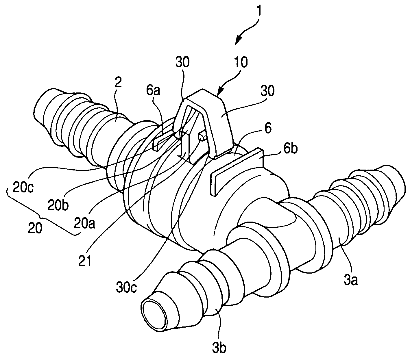
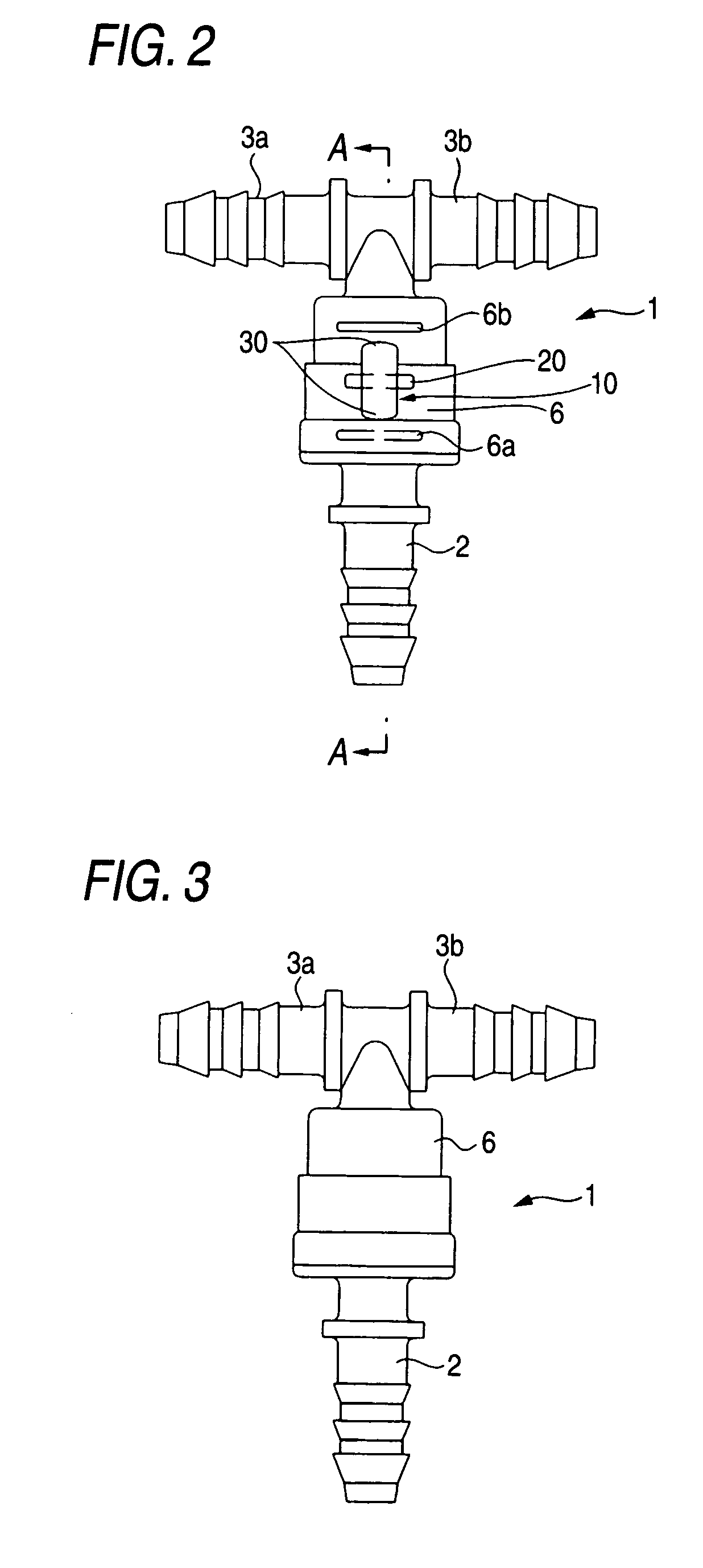
[0038] FIGS. 1 to 12 show an embodiment in which a clip of the invention is applied to a clip for attaching a check valve which is disposed in a fuel tank of an automobile. FIG. 1 is a perspective view of the check valve; FIG. 2 is a front elevational view of the check valve; FIG. 3 is a rear view of the check valve; FIG. 4 is a right side elevational view of the check valve; FIG. 5 is a left side elevational view of the check valve; FIG. 6 is a plan view of the check valve; FIG. 7 is a bottom view of the check valve; FIG. 8 is a cross-sectional view taken in the direction of arrows along line A-A in FIG. 2; FIG. 9 is an enlarged view of a clip portion; FIG. 10 is a cross-sectional view taken in the direction of arrows along line B-B in FIG. 9; FIG. 11 is an explanatory diagram illustrating the deflecting operation of resiliently retaining pieces of the clip; and FIG. 12 i...


PUM


Abstract

A clip which is inserted and engaged in an attaching hole includes: a proximal portion 6 for abutting against one surface around a peripheral edge of the attaching hole; a stem extending from the proximal portion and adapted to be inserted in the attaching hole; and a pair of resiliently retaining pieces extending from a distal end portion of the stem toward the proximal portion in the form of an anchor and adapted to engage an edge of the attaching hole in another surface. At least one projection is formed on a side wall of the stem opposing the resiliently retaining piece, and an amount of deflection of the resiliently retaining piece is restricted by the projection.

Description

BACKGROUND OF THE INVENTION [0001] 1. Field of the Invention [0002] The present invention relates to a clip which is used when an attaching member such as a valve is attached to a mating member, for example, a fuel tank of an automobile or the like. [0003] 2. Description of the Related Art [0004] Various valves such as cutoff valves and check valves are attached in and outside a fuel tank of an automobile. To attach this valve member, a clip made of a synthetic resin or the like is formed on the valve member. The valve member is conventionally attached to the mating member by causing this clip to be engaged in an attaching hole in the mating member. [0005] As shown in FIG. 13, a conventional clip 100 has a proximal portion 101 formed on an attaching member; a stem 102 extending from this proximal portion 101; and a pair of resiliently retaining pieces 103 extending from a distal end portion of the stem 102 toward the proximal portion in the form of an anchor and adapted to engage an...

Claims


Application Information

Patent Timeline
Patent Type & Authority Applications(United States)
IPC IPC(8): F16B2/20F16B5/06F16B19/00F16B21/08
CPCF16B21/088F16B5/0685F16B2/20
Inventor YONEZAWA, KENJI
Owner PIOLAX CO LTD
Why Eureka
Try Eureka