Connector housing and connector

a technology of connecting parts and connectors, applied in the direction of coupling bases/cases, coupling devices, two-part coupling devices, etc., can solve the problems of affecting the high frequency characteristic of coaxial cables, difficult to press only the operating pieces, and characteristic impedance disturbance, so as to achieve easy displaced, improve the ease of unlocking operation, and the effect of large pressing surface width

Active Publication Date: 2020-08-04
SUMITOMO WIRING SYST LTD
View PDF35 Cites 8 Cited by
  • Summary
  • Abstract
  • Description
  • Claims
  • Application Information

AI Technical Summary

Benefits of technology

[0007]The lock arm can be displaced easily in the unlocking direction by pressing the pressing surface disposed on the rear end part of the lock arm. Thus, the ease of an unlocking operation can be improved.
[0008]The coupling portion of one embodiment includes two arms coupled to both left and right sides of the lock arm, and the pressing surface extends to the arms. According to this configuration, a large width of the pressing surface is ensured. Thus, fingers can be placed on the pressing surface more easily and, hence, the unlocking operation is facilitated.
[0009]The pressing surface may have a cutout configured to allow the rear end part of the lock arm to escape when the pressing surface is pressed. Thus, a deflection space for the lock arm can be smaller, and a height reduction of the connector housing can be realized.
[0010]The housing body may have a protecting portion that covers a side of the lock arm opposite to the unlocking direction in an intermediate part of the lock arm in the front-rear direction, and the pressing surface may be located behind the protecting portion. Thus, the intermediate part of the lock arm in the front-rear direction cannot be pressed inadvertently in the unlocking direction, while still permitting the pressing surface to be pressed easily.
[0011]The terminal fitting may be a coaxial terminal to be connected to an end of a coaxial cable. A coaxial connector that rattles in a properly connected state causes a characteristic impedance disturbance and affects a high frequency characteristic of the coaxial cable. However, according to this configuration, the lock arm of the connector housing is supported on both ends. Thus, the rattling of the connector in the properly connected state is reduced for advantageously suppressing a high frequency characteristic variation.

Problems solved by technology

Thus, it is difficult to press only the operating piece.
A coaxial connector that rattles in a properly connected state causes a characteristic impedance disturbance and affects a high frequency characteristic of the coaxial cable.

Method used


Image

  • Connector housing and connector
  • Connector housing and connector
  • Connector housing and connector

Examples


Embodiment Construction

[0020]An embodiment of the invention is described in detail with reference to FIGS. 1 to 8.

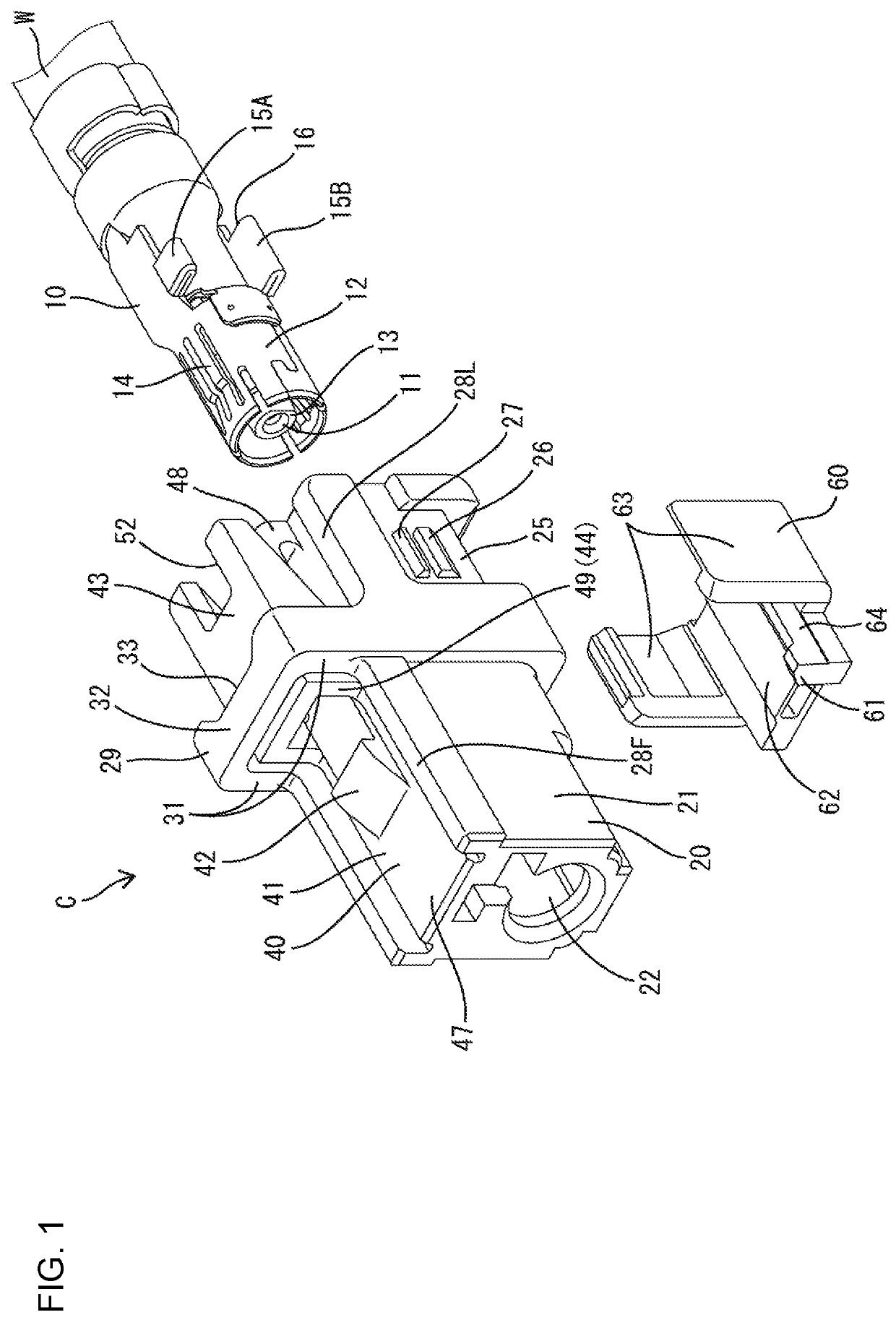
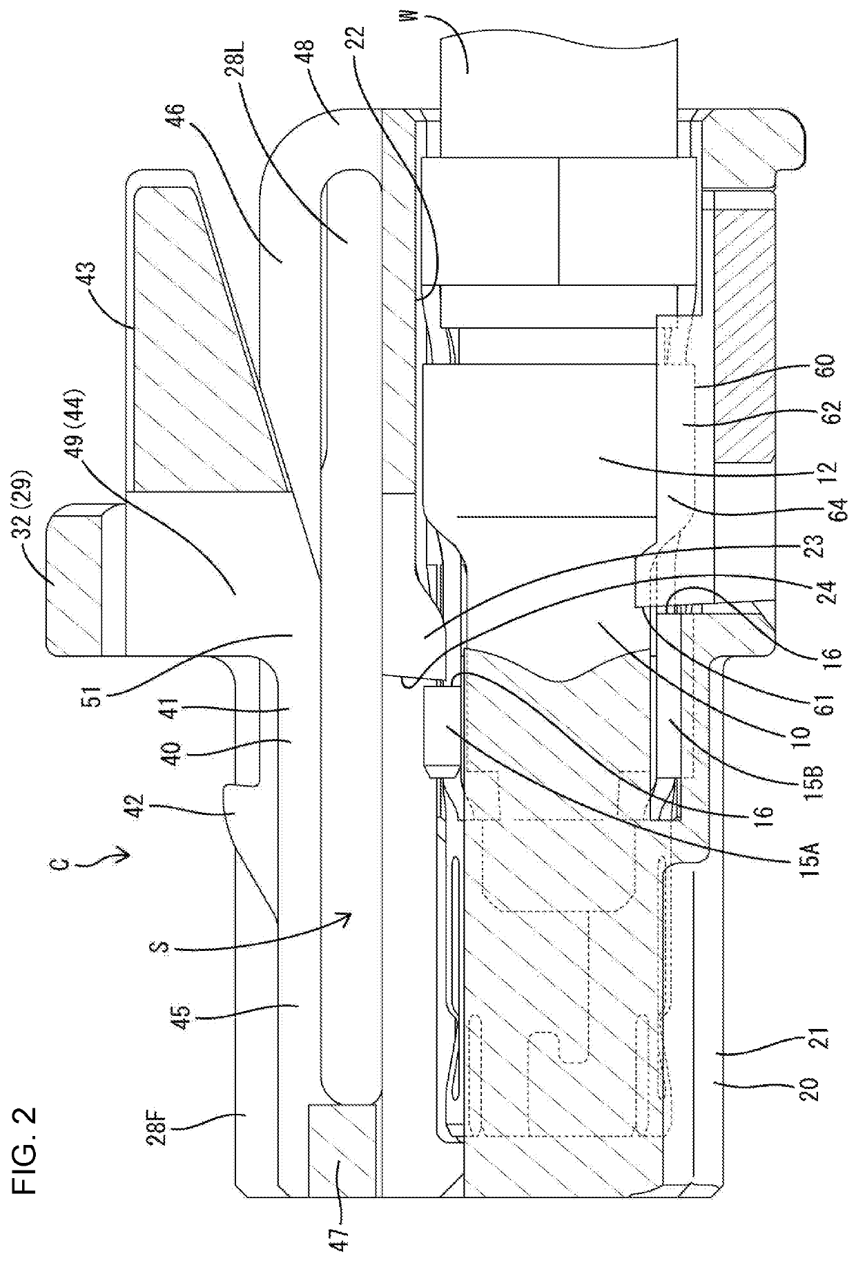
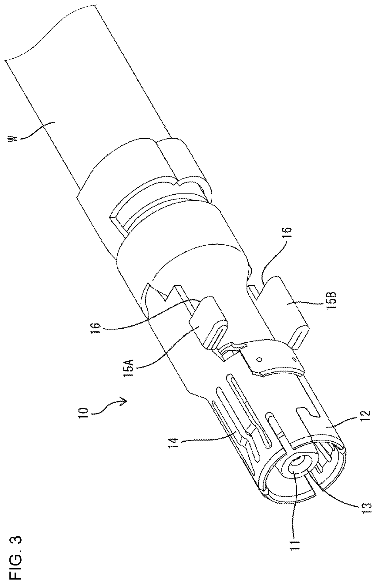
[0021]A connector C in this embodiment includes a terminal fitting 10 connected to an end part of a cable W and a connector housing 20 for accommodating the terminal fitting 10. The connector C is a female connector connectable to an unillustrated mating male connector. In the following description, in each constituent member, a connection surface (left-front of FIG. 1) of the connector C to a mating connector is referred to as a front, an opposite side (right-back of FIG. 1) is referred to as a rear, and an upper side (side where a lock arm 40 is provided) and a lower side of FIG. 1 are referred to as an upper side and a lower side.

[0022]The cable W is a coaxial cable including a conductive center conductor, an insulating coating surrounding the outer periphery of the center conductor, a conductive shield layer surrounding the outer periphery of the coating and an insulating sheath surroundin...


PUM


Abstract

A connector housing (20) includes a housing body (21) to which a mating connector housing is to be fit from front. A lock arm (40) has front and rear ends fixed to the housing body (21). A lock (42) is provided in a central part of the lock arm (40) in the front-rear direction and is configured to lock the mating connector housing. A pressing surface (43) is on a rear end part of the lock arm (40) and is configured to displace the lock (42) in an unlocking direction by being pressed. A coupling portion (44) couples the pressing surface (43) to the central part of the lock arm (40) in the front-rear direction.

Description

BACKGROUNDField of the Invention[0001]The invention relates to a connector housing and a connector.Related Art[0002]A connector housing conventionally includes a housing body with a front end and a mating connector housing is fit to the housing body from the front. The housing has a lock arm for locking the mating connector housing in a properly connected state. For example, Japanese Unexamined Patent Publication No. 2001-319732 discloses a connector housing with a lock arm supported at opposite front and rear ends to a housing body. The support of the lock arm on both ends reduces rattling in the front-rear direction at the time of connection to a mating connector housing as compared to a cantilevered lock arm. A lock protrusion is provided on the upper surface of this lock arm at a position somewhat closer to a front end than a central part in the front-rear direction. An operating piece for an unlocking operation projects at a position slightly behind the lock protrusion. The ope...

Claims


Application Information

Patent Timeline
Patent Type & Authority Patents(United States)
IPC IPC(8): H01R13/639H01R13/627H01R13/6582H01R13/436H01R24/40H01R13/50H01R9/05
CPCH01R13/6272H01R24/40H01R13/6582H01R13/50H01R13/639H01R9/05H01R13/4362H01R13/6335
Inventor KANEMURA, KEISUKEHARA, TERUOMATSUDA, HIDEKAZUHIRANO, AINAKANISHI, YUICHIMITSUI, SHOHEI
Owner SUMITOMO WIRING SYST LTD
Why Eureka
Try Eureka