Support structure for a load-bearing device

a support structure and load-bearing technology, applied in the direction of force measurement, force/torque/work measurement apparatus, instruments, etc., can solve the adverse effect of horizontal force on measurement accuracy, scales, and other problems, so as to reduce the horizontal force components, reduce the effective height, and reduce the effect of horizontal for

Active Publication Date: 2006-02-28
AVERY WEIGH-TRONIX
View PDF6 Cites 2 Cited by
  • Summary
  • Abstract
  • Description
  • Claims
  • Application Information

AI Technical Summary

Benefits of technology

[0008]A support mechanism for reducing the horizontal force components on load measurement is presented. The support mechanism includes a structure having two ends with non-uniform radii of curvature separated by a distance. The two ends may include oblate spheroid surfaces. The ends of the structure contact a force-sensor coupling element and a base-coupling element, forming two interfaces. Each interface includes a contact area between a convex surface and a concave surface. When a horizontal force is applied, the contact area at each interface shifts, causing the structure to tip from the vertically aligned position that it is in when no horizontal force is applied. Compared to conventional support mechanisms, the support mechanism of the invention has a lower effective height because the interfaces between oblate spheroid surfaces allow a larger angle of deflection than spherical or flat interfaces while still limiting contact stress levels. Also, the surfaces with non-uniform radii of curvature interfaces allow deflection to occur with less wear and tear at the interfaces compared to the spherical- and flat-interfaced support structures. The support mechanism may be used, for example, in a load cell.
[0009]In another aspect, the invention is a method of reducing the effect of diverse forces or horizontal force on load measurement by using interfaces of two oblate spheroidal surfaces or surfaces with non-constant curvature. More specifically, the method includes coupling a structure to a first force coupling mechanism by placing a first surface with non-constant curvature in contact with a first counterpart surface with non-constant curvature to form a first contact surface. Similarly, a second contact surface is formed by coupling the structure to a second force coupling mechanism. This coupling is done by placing a second surface of the structure in contact with a second counterpart surface, wherein both the second surface and the second counterpart surface have a non-constant curvature. The first and second contact surfaces shift positions when the structure tips from a vertically aligned position in response to horizontal force. The structure returns to its original vertically aligned position upon removal of the horizontal force with minimal oscillation.

Problems solved by technology

These scales, while reducing the adverse effect on measurement accuracy that is caused by horizontal forces, are expensive.
The high cost associated with these scales are at least partly due to the massive support structures that are needed to suspend the flexible tension elements located between the load bearing structures and the load cells to reduce diverse forces horizontal forces between the load cells.
Although scales exist that do not require these massive and expensive support structures, these scales have other problems.
However, these scales are problematic in that they do not dampen the vibration or absorb energy adequately to prevent undesirable effects to the scale and on the force measurement when the scale is disturbed by the load.
Although they can be made to dampen vibration and absorb adequate energy, doing so requires equipping these scales with an expensive check-rod system.
These load cells must have large pads to support heavy loads because of the low load bearing strength of rubber pads.
Otherwise, twisting and bending of the load cells due to diverse forces create errors in the load cell outputs.

Method used


Image

  • Support structure for a load-bearing device
  • Support structure for a load-bearing device
  • Support structure for a load-bearing device

Examples


Embodiment Construction

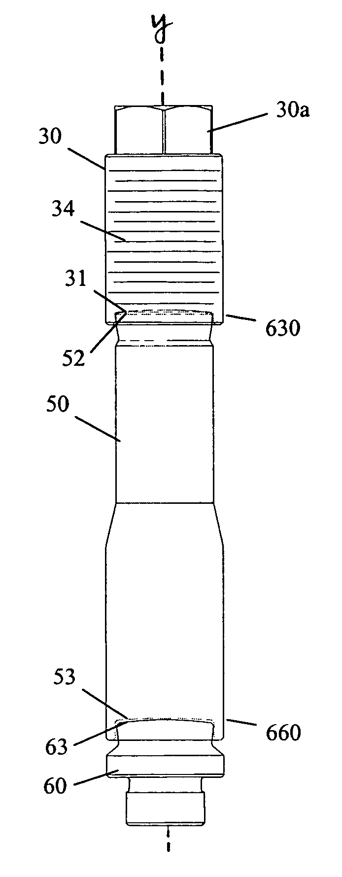
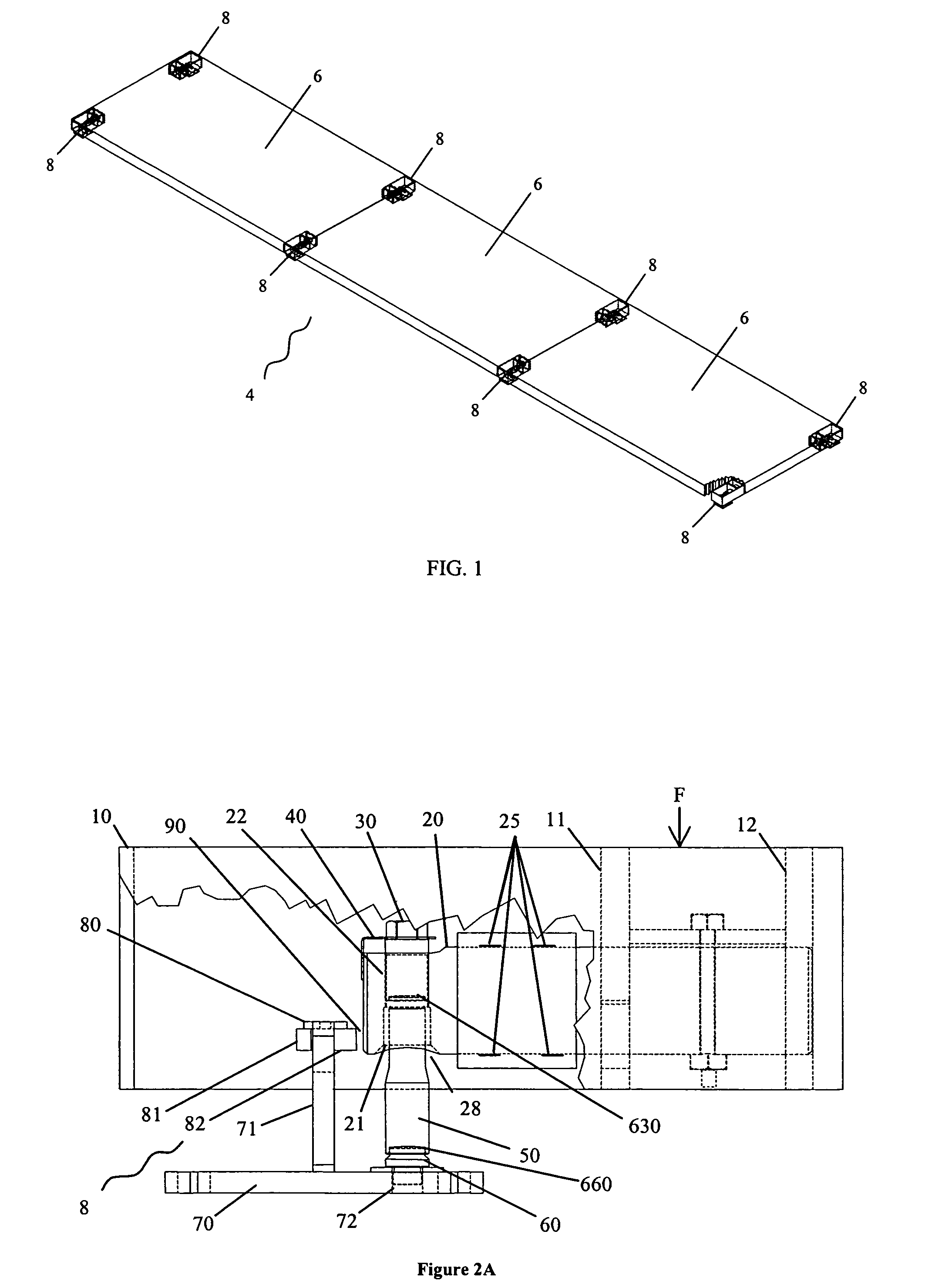
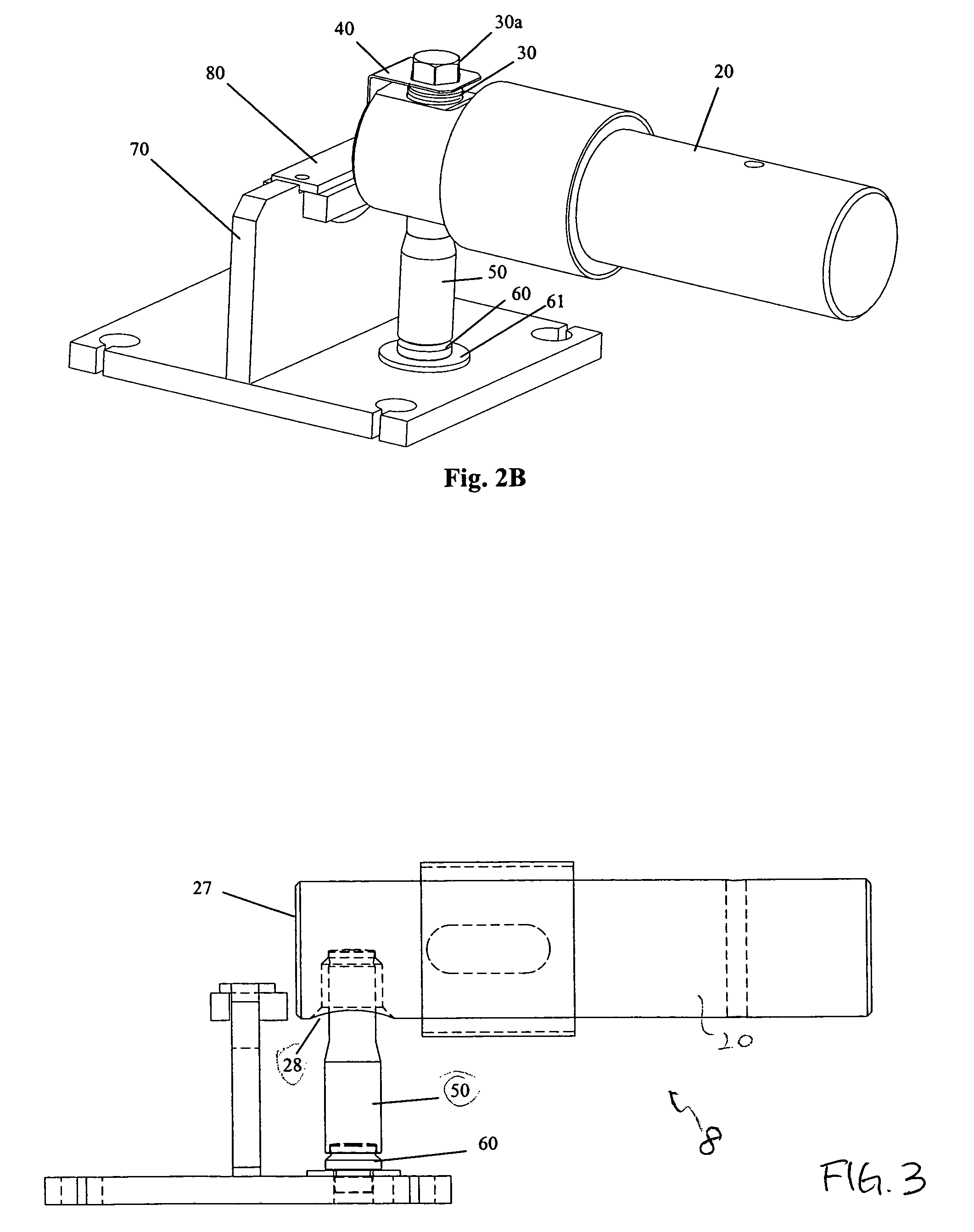
[0030]Embodiments of the invention are described herein in the context of a load cell and more specifically in the context of a multi-load-cell scale. However, it is to be understood that the embodiments provided herein are just preferred embodiments, and the scope of the invention is not limited to the applications or the embodiments disclosed herein. For example, the supporting structure may be used in any application where it is desirable to reduce diverse forces that act in a direction other than the direction of interest. Also, although cylindrical embodiments of the support structure are disclosed, the support structure may have any shape that suits a particular application. Although oblate spheroid surfaces are disclosed, a person of ordinary skill in the art will understand that any suitable rotated surface with a non-constant curvature, such as parabolic, hyperbolic, sinusoidal, and exponential surfaces, may function as the invention depending on the application and deforma...


PUM

PropertyMeasurementUnit
radii of curvatureaaaaaaaaaa
forceaaaaaaaaaa
forcesaaaaaaaaaa

Abstract

A mechanism for reducing horizontal force in load measurement is presented. The mechanism includes a structure having surfaces of nonuniform radii of curvature (e.g., oblate spheroid surfaces) at both ends. The ends of the structure contact a force-sensor coupling element and a base-coupling element, forming two interfaces. Each interface includes a contact area between a convex surface and a concave surface. When a horizontal force is applied, the contact area at each interface shifts, allowing the structure to tip from the vertically aligned position that it is in when no horizontal force is applied. Compared to conventional mechanisms, the structure of the invention has a lower effective height because interfaces between oblate spheroid surfaces allow a larger angle of deflection than flat interfaces. The oblate spheroid interfaces also allow deflection to occur with less wear and tear at the interfaces compared to the flat-interfaced structures.

Description

FIELD OF THE INVENTION[0001]The invention relates generally to a load-bearing device for force transfer and particularly to a scale support element for improved measurement of force.BACKGROUND OF THE INVENTION[0002]Various load measuring devices and scales are known in the art. For example, U.S. Pat. No. 3,650,340 to Richard S. Bradley discloses a bending-beam structured load cell that is resistant to torque, moment, and end-forces, all of which affect the accuracy of the load cell. Most of the currently available scales generally depend on the stability of the loaded structure between the load cells for output stability and reduction of horizontal forces. For example, scales made by Weigh-Tronix utilizing multiple load cells provide chain links to reduce horizontal forces between load cells and absorb the energy from horizontal movement of the load on the scale. Other scales provide vertical cables to reduce diverse forces such as horizontal forces, thereby providing a substantiall...

Claims


Application Information

Patent Timeline
Patent Type & Authority Patents(United States)
IPC IPC(8): G01L1/04G01N3/04
CPCG01N3/04G01N2203/0482
Inventor JOHNSON, THOMAS H.HALL, ROBERT J.
Owner AVERY WEIGH-TRONIX
Why Eureka
Try Eureka