

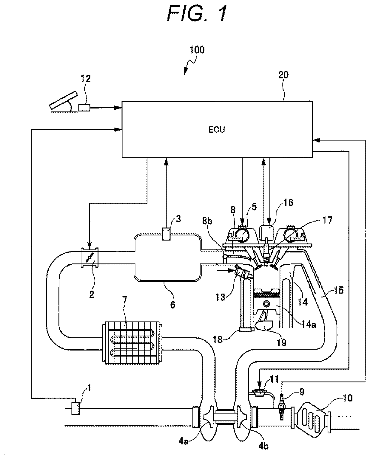
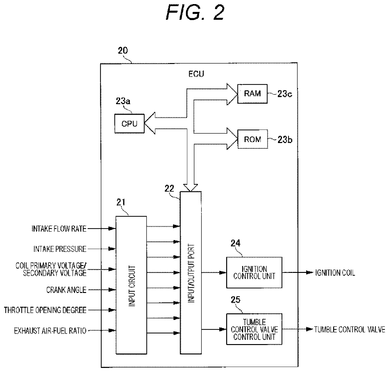
Internal Combustion Engine Control Device
a control device and combustion engine technology, applied in the direction of electric control, automatic control, ignition control, etc., can solve problems such as misfires, and achieve the effect of reducing measurement loads
- Summary
- Abstract
- Description
- Claims
- Application Information
AI Technical Summary
Benefits of technology
Problems solved by technology
Method used
Image

Examples
first embodiment
2-1. First Embodiment
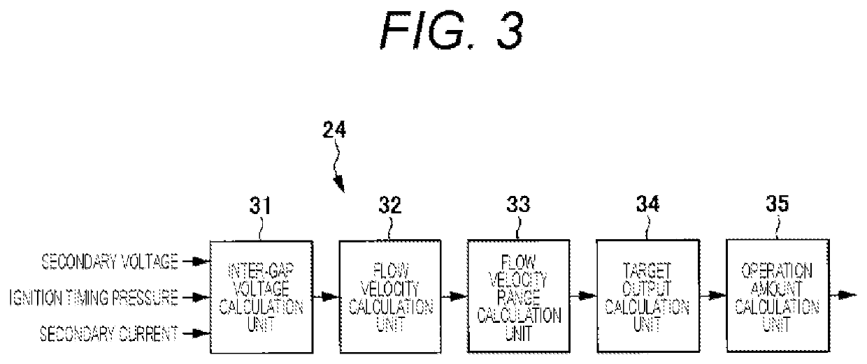
[0060]Next, a first embodiment of the ignition control unit will be described with reference to FIGS. 3 to 12.
[0061]FIG. 3 is a control block diagram illustrating an outline of discharge energy control in the ignition control unit.
[0062]As illustrated in FIG. 3, the ignition control unit 24 includes an inter-gap voltage calculation unit 31, a flow velocity calculation unit 32, a flow velocity range calculation unit 33, a target output calculation unit 34, and an operation amount calculation unit 35.
[0063]The inter-gap voltage calculation unit 31 obtains a voltage between a center electrode 17a and a ground electrode 17b (see FIG. 4) (referred to as an inter-gap below) of the ignition plug 17 based on the secondary voltage applied to the ignition coil 16, the secondary current, and the in-cylinder pressure that is the pressure in the hollow of the cylinder 4 at the ignition timing.
[0064]The inter-gap voltage calculation unit 31 obtains a voltage under a condition...
second embodiment
2. Second Embodiment
[0158]Next, an ignition control unit according to a second embodiment will be described with reference to FIGS. 14 to 17.
[0159]FIG. 14 is a control block diagram illustrating an outline of discharge energy control in the ignition control unit according to the second embodiment.
[0160]As illustrated in FIG. 14, an ignition control unit 24B includes an inter-gap voltage calculation unit 131, a flow velocity calculation unit 132, a flow velocity correction unit 133, a flow velocity range calculation unit 134, a target output calculation unit 135, and an operation amount calculation unit 136. That is, the ignition control unit 24B according to the second embodiment is obtained by providing the flow velocity correction unit 133 in the ignition control unit 24 according to the first embodiment. Therefore, the flow velocity correction unit 133 will be described here.
[0161]The air flow rate measured by the air flow sensor 1 is output to the flow velocity correction unit 1...
third embodiment
3. Third Embodiment
[0181]Next, an ignition control unit and a tumble-control-valve control unit according to a third embodiment will be described with reference to FIGS. 18 to 21.
[0182]FIG. 18 is a control block diagram illustrating an outline of discharge energy control in the ignition control unit and the tumble-control-valve control unit according to the third embodiment.
[0183]As illustrated in FIG. 18, a tumble-control-valve control unit 177, a tumble-control-valve state determination unit 178, and an ignition-plug state determination unit 179 are connected to an ignition control unit 24C. Similarly to the ignition control unit 24B according to the second embodiment, the ignition control unit 24C includes an inter-gap voltage calculation unit 171, a flow velocity calculation unit 172, a flow velocity correction unit 173, a flow velocity range calculation unit 174, a target output calculation unit 175, and an operation amount calculation unit 176. The flow velocity range calculat...
PUM
 Abstract
Description
Claims
Application Information