Insertable thermotic module for self-heating cans

a thermotic module and self-heating technology, applied in the field of self-heating cans, can solve the problems of reactant typically not being placed in the cavity before, consumption of contents, and subjecting to the normal sterilization process, and achieves low vicat softening point and sufficient thinness

Inactive Publication Date: 2006-02-28
HOT CAN INTPROP
View PDF48 Cites 45 Cited by
  • Summary
  • Abstract
  • Description
  • Claims
  • Application Information

AI Technical Summary

Problems solved by technology

The user inverts the container and, when the contents have reached the desired temperature, consumes the contents.
One of the disadvantages associated with prior self-heating containers which place the chemical reactants directly into the cavity (i.e. an integral thermic module) is that the reactants typically cannot reliably be placed within the cavity before the container is filled with a food or beverage and subjected to the normal sterilization process.
This is because the heat of the sterilization process may damage the reactants.
It is generally not desirable to fill, sterilize, and pack the thermic modules into the containers at the same location.
This is because the risk of contamination from the chemical reactants and because of the expense operating the module packing step in the same sterile environment required for filling and sealing the food or beverage in the containers.
While patents such as U.S. Pat. No. 6,134,894 to Searle, et al. have disclosed separately formed modules which insert into the cavity of the container, these prior art modules still possess many disadvantages.
However, it is often difficult to manufacture thermic module to the exact tolerance which allows the module to readily slide into the cavity and at the same time perfectly fit against the internal walls of the cavity.
And while metals such as aluminum have good heat transfer characteristics, inevitably an air gap occurs between the module sidewalls and the internal walls of the cavity and acts as an insulating barrier.
Prior art devices such as discussed in the Searle patent suggest using gels to fill air gaps, but gels have limited shelf-life because they tend to dry out.
However, it has generally been accepted in the industry that the low thermal conductivity of plastics renders it totally impractical for a plastic thermic module to heat a container's contents to the desired 40° C. in less than 180 seconds.
It is not believed that the prior art separately formed thermic modules are capable of reliably achieving this temperature / time requirement, particularly when dealing with standard sized soft drink cans.
Another disadvantage existing in prior art devices is the process for manufacturing containers having a thermic module.

Method used


Image

  • Insertable thermotic module for self-heating cans
  • Insertable thermotic module for self-heating cans
  • Insertable thermotic module for self-heating cans

Examples


Embodiment Construction

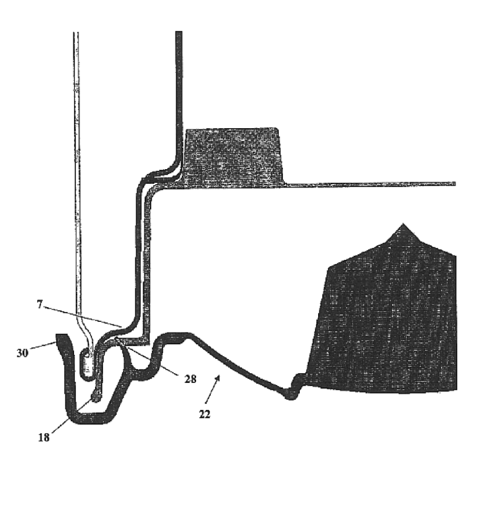
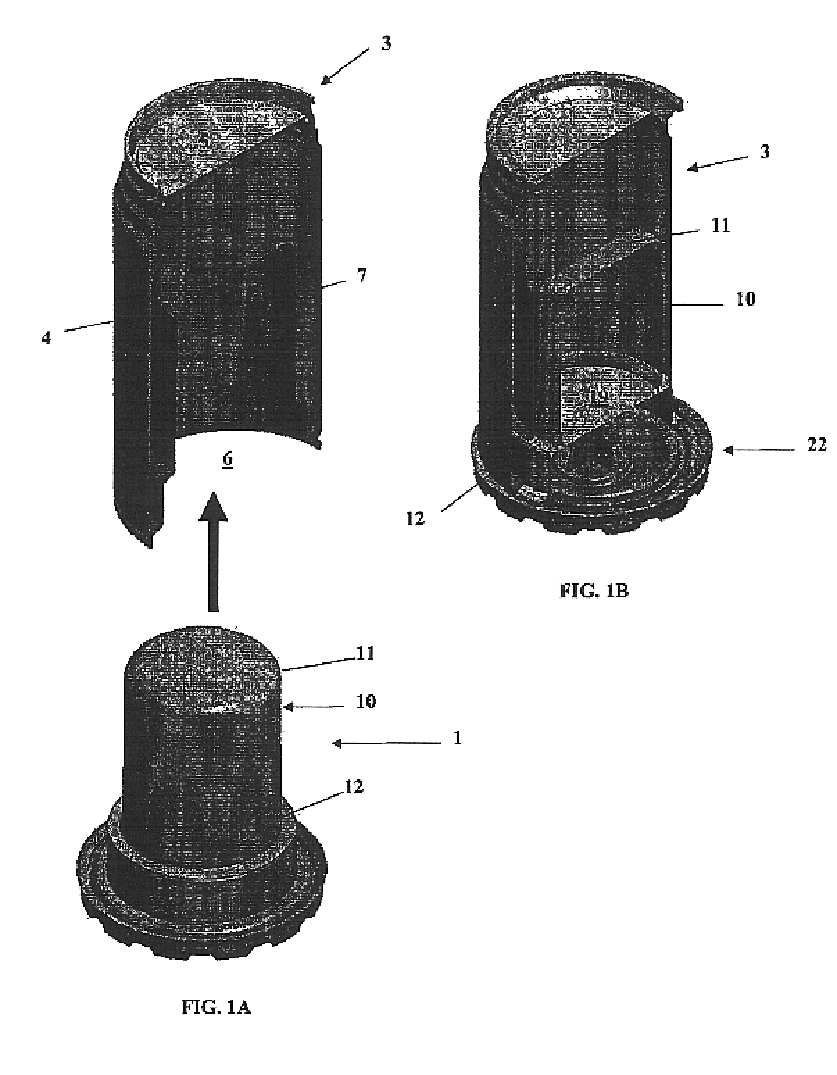
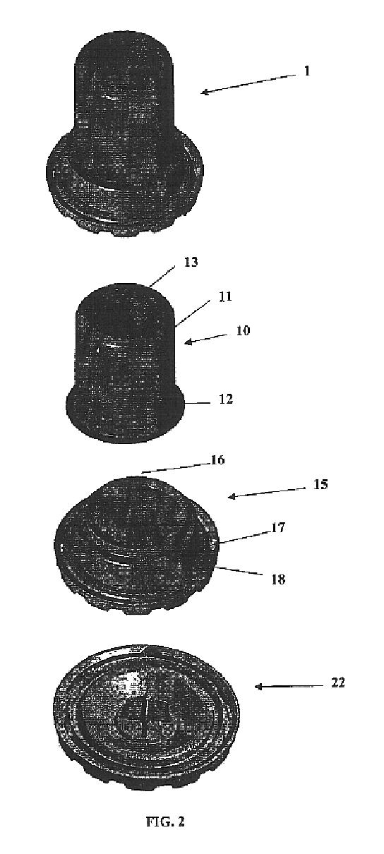
[0044]FIG. 1A illustrates a self-heating container 3 formed by outer sidewalls 4, top 5, and to inner wall 7. While not shown, it will be understood that top 5 may include a conventional pull tab or pop top opening such as found on typical soda cans. It can be seen how inner wall 7 is generally cylindrical and forms a chamber or cavity 6. While not explicitly shown, the interior wall of cavity 6 may be fluted to provide more surface area to facilitate heat transfer from the thermic module 1 to the contents of container 3. Thermic module 1 is sized such that it can be inserted into cavity 6 as suggested by FIG. 1B. The main components of thermic module 1, upper cup 10, lower cup 15, and end cap 22 are best seen in FIGS. 1B and 2. First or upper cup 10 will be formed of a generally cylindrical sidewall 11 and integral top 13. Upper cup 10 will also have a cup lip 12 extending around the base of sidewall 11. It can be seen in FIG. 1B how the interior of upper cup 10 is hollow. FIG. 2 a...


PUM

PropertyMeasurementUnit
internal pressureaaaaaaaaaa
temperaturesaaaaaaaaaa
pressureaaaaaaaaaa

Abstract

A self-heating container which comprises a container body having an internal beverage section and a thermic cavity. A liquid reactant is positioned in a first section of the thermic cavity and a solid reactant positioned in a second section of the thermic cavity. The solid reactant includes at least 70% by weight CaO and at least 5% by weight of a carbonate from the group consisting of MgCO3, CaCO3, SrCO3, BaCO3, and RaCO3.

Description

[0001]This application is a Continuation-In-Part to U.S. application Ser. No. 10 / 003,877 filed on Oct. 25, 2001, which claims benefit of Provisional 60 / 288,184, filed May 2, 2001, which is incorporated herein by reference.BACKGROUND OF THE INVENTION[0002]The present invention relates to self-heating cans or other containers holding beverages, food, medicine, epoxy resins and other materials that it is desired to heat before consuming or using. In particular, the present invention relates to an insertable themotic module for such self-heating containers.[0003]Containers may have integral or separate insertable modules for warming materials in the container, such as Japanese sake, coffee, or soup. Examples of such self-heating containers with integral thermic modules are disclosed in U.S. Pat. Nos. 5,461,867 and 5,626,022, issued to Scudder et al and an example of a separately insertable module is disclosed in U.S. Pat. No. 6,134,894 to Searle, et al. Such containers typically include...

Claims


Application Information

Patent Timeline
Patent Type & Authority Patents(United States)
IPC IPC(8): F24J1/00A23L3/02A23L3/10A47J36/28B65D81/34B65D81/38C09K5/18F24V30/00
CPCA23L3/02A23L3/10A47J36/28C09K5/18B65D81/3846B65D81/3484B65D2205/00B65D2581/3436
Inventor KOLB, KENNETH W.
Owner HOT CAN INTPROP
Why Eureka
Try Eureka