Method and apparatus for routing cable in existing pipelines

a technology for routing cables and existing pipelines, applied in mechanical devices, underground pipes, sewer pipes, etc., can solve the problems of difficult cable routing, exceptionally expensive underground routing, and general inapplicability of boring machines

Inactive Publication Date: 2006-02-28
ULC TECH LLC
View PDF23 Cites 29 Cited by
  • Summary
  • Abstract
  • Description
  • Claims
  • Application Information

AI Technical Summary

Problems solved by technology

In urban environments, however, cable routing is a difficult feat.
Underground routing is exceptionally expensive, when available at all, since adding additional tunnels or conduit often involves tearing up lengthy expanses of street or pavement.
Boring machines are generally not practical, as the subsurface is already laced with numerous tunnels, conduits, subways, water lines, sewer lines, gas lines, and the like.
However, cable cannot merely be introduced into such environments and left to freely move.
Continuous movement over long periods can generate fatigue and work-hardening in metal conductor-containing cables.
Sudden movements or the development of sharp bends or kinks can be destructive of fiber optic cables.
Moreover, despite the numerous advances in cable insulation, covering, and armor, it is still not desirable, as a general rule, that the cable be continually immersed in liquid.
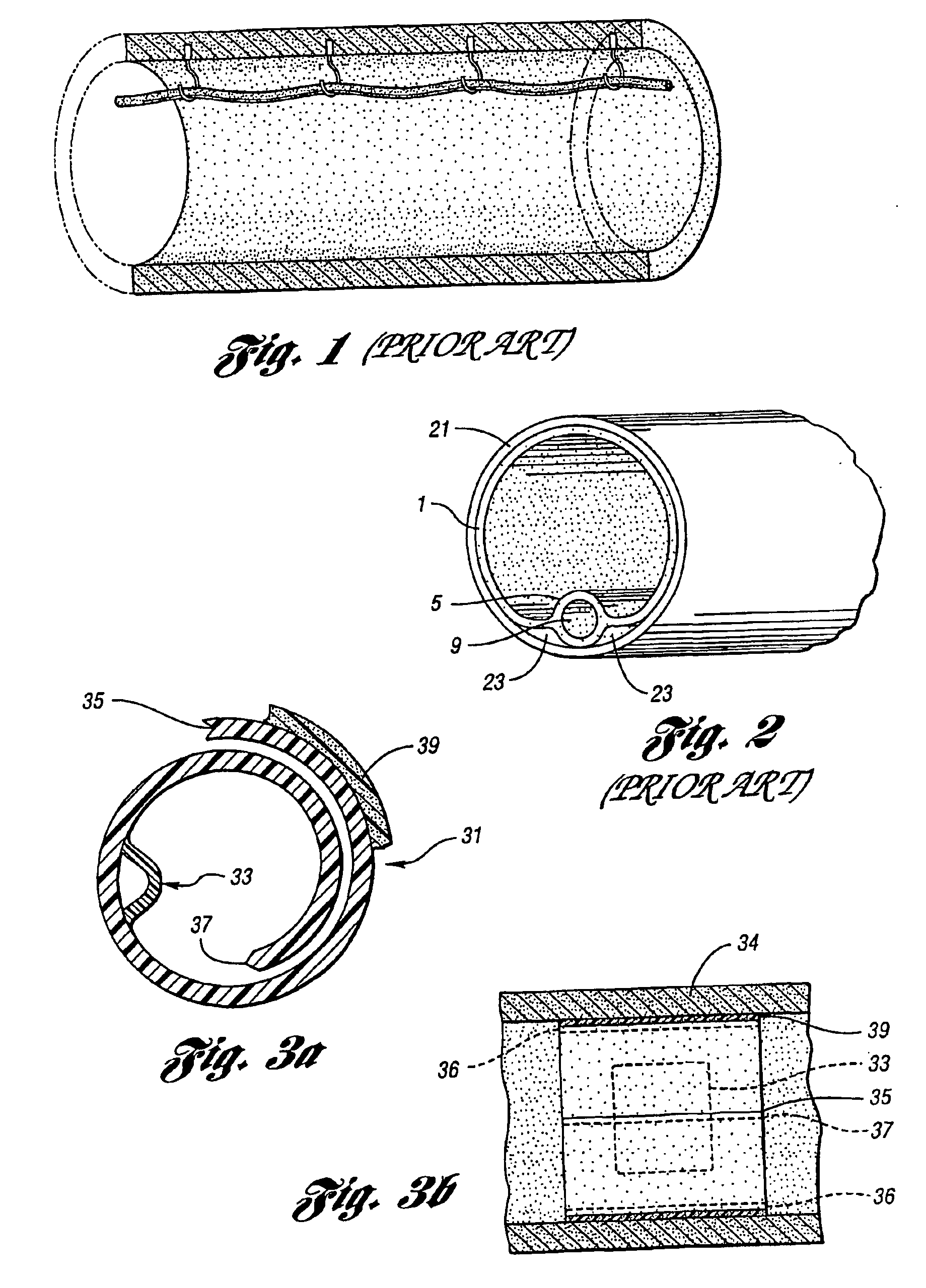
However, the method is not satisfactory for pipelines which are not totally in need of renovation.
Installation of the J-hooks is problematic, however.
Due to the nature of sewer pipe material of construction and its constant exposure to wet or moist environments, many installation failures are to be expected, as is also occasional damage to the pipe itself, including perforation, cracking, etc.
Moreover, due to little support in directions transverse to the stem of the J-hook stem, the hooks may be removed by occasional passage of obstructions down the pipe, or by collision with sewer cleaning or renovating robots, etc.
However, the robotic system for expanding the bands is complex and expensive, the bands provide little lateral support, and thus are subject to cocking out of position.

Method used


Image

  • Method and apparatus for routing cable in existing pipelines
  • Method and apparatus for routing cable in existing pipelines
  • Method and apparatus for routing cable in existing pipelines

Examples


Embodiment Construction

[0036]In the specification which follows, the term “cable structure” may be used to denote either a “cable” per se or a conduit for containing one or more “cables.” Individual “cable” types may be denoted as “wire cables” or “optical cables” as necessity dictates. The types of wire cables and optical cables which may be routed employing the present invention are not limited. These may be electrical supply cables, i.e. for direct or alternating voltage for supply to households, businesses, machinery, etc., i.e. single, two, or multiple phase alternating current of any voltage, generally 110 v to 440 v; low voltage wiring, especially for control devices, for example 24 volt alternating or direct current.

[0037]Preferably, however, the “wire” cables are telecommunications cables such as those customarily used in the telecommunications industry. These may be of the coaxial type, single strands, sheathed cables containing a multiplicity of individual insulated strands or twisted pairs, et...


PUM


Abstract

Supports for routing cables in existing pipelines are flexible cable supports containing minimally one hollow passage to receive a cable, and are installed between an existing pipeline inner wall and a structural liner. The cable supports have an elongate cross-section transverse to their length and are of sufficient flexibility to conform to the interior wall of the pipeline.

Description

CROSS-REFERENCE TO RELATED APPLICATION[0001]This application claims the benefit of U.S. provisional application Ser. No. 60 / 292,248 filed May 18, 2001, is a continuation in part of and also claims priority to U.S. application Ser. No. 09 / 910,244 filed Jul. 20, 2001, now U.S. Pat. No. 6,712,556, and PCT Appln. No. PCT / US02 / 015989 filed May 20, 2002.BACKGROUND OF THE INVENTION[0002]1. Field of the Invention[0003]The present invention pertains to routing cable within existing pipelines, and to apparatus suitable for use therein.[0004]2. Background Art[0005]In rural environments, routing of a variety of cable, particularly communications cable, may be accomplished by overhead routing on “telephone” poles or by routing underground in newly installed conduits or tunnels. In suburban environments, both overhead and underground routing is also commonplace, the latter particularly in the case of new construction.[0006]In urban environments, however, cable routing is a difficult feat. Often, ...

Claims


Application Information

Patent Timeline
Patent Type & Authority Patents(United States)
IPC IPC(8): F16L7/00E03F3/04E03F3/06H02G9/06
CPCE03F3/04E03F3/06H02G9/06E03F5/022E03F2003/065
Inventor PENZA, G. GREGORY
Owner ULC TECH LLC
Why Eureka
Try Eureka