Shaft for anchoring a hip joint prosthesis in the femur

a hip joint and femur technology, applied in the field of profiled shafts for anchoring hip joints in the femur, can solve the problem of comparatively large empty spaces in the corner regions, and achieve the effect of reducing the number of screws

Inactive Publication Date: 2006-02-28
PLUS ORTHOPEDICS
View PDF30 Cites 26 Cited by
  • Summary
  • Abstract
  • Description
  • Claims
  • Application Information

AI Technical Summary

Benefits of technology

[0006]The purpose of the beveled surfaces (facets) is to achieve a better fit of the trochanter-wing region of the profile shaft when it is seated in the femoral opening.
[0009]The object of the present invention is to create a profiled shaft of the above-mentioned kind, for the anchoring section of a hip-joint prosthesis in the femur, such that the empty space in the trochanter-wing region can be substantially reduced by particularly simple measures.
[0012]Furthermore, an especially improved filling of the empty space in the trochanter-wing region can be achieved by forming a beveled surface (Facet) at the transition between the lateral surface of the shaft and the anterior (broad) surface, and between the lateral surface of the shaft and the posterior (broad) surface of the shaft.

Problems solved by technology

However, this specification of the facet angle has proved to produce comparatively large empty spaces in the corner regions of the trochanter wing.

Method used


Image

  • Shaft for anchoring a hip joint prosthesis in the femur
  • Shaft for anchoring a hip joint prosthesis in the femur
  • Shaft for anchoring a hip joint prosthesis in the femur

Examples


Embodiment Construction

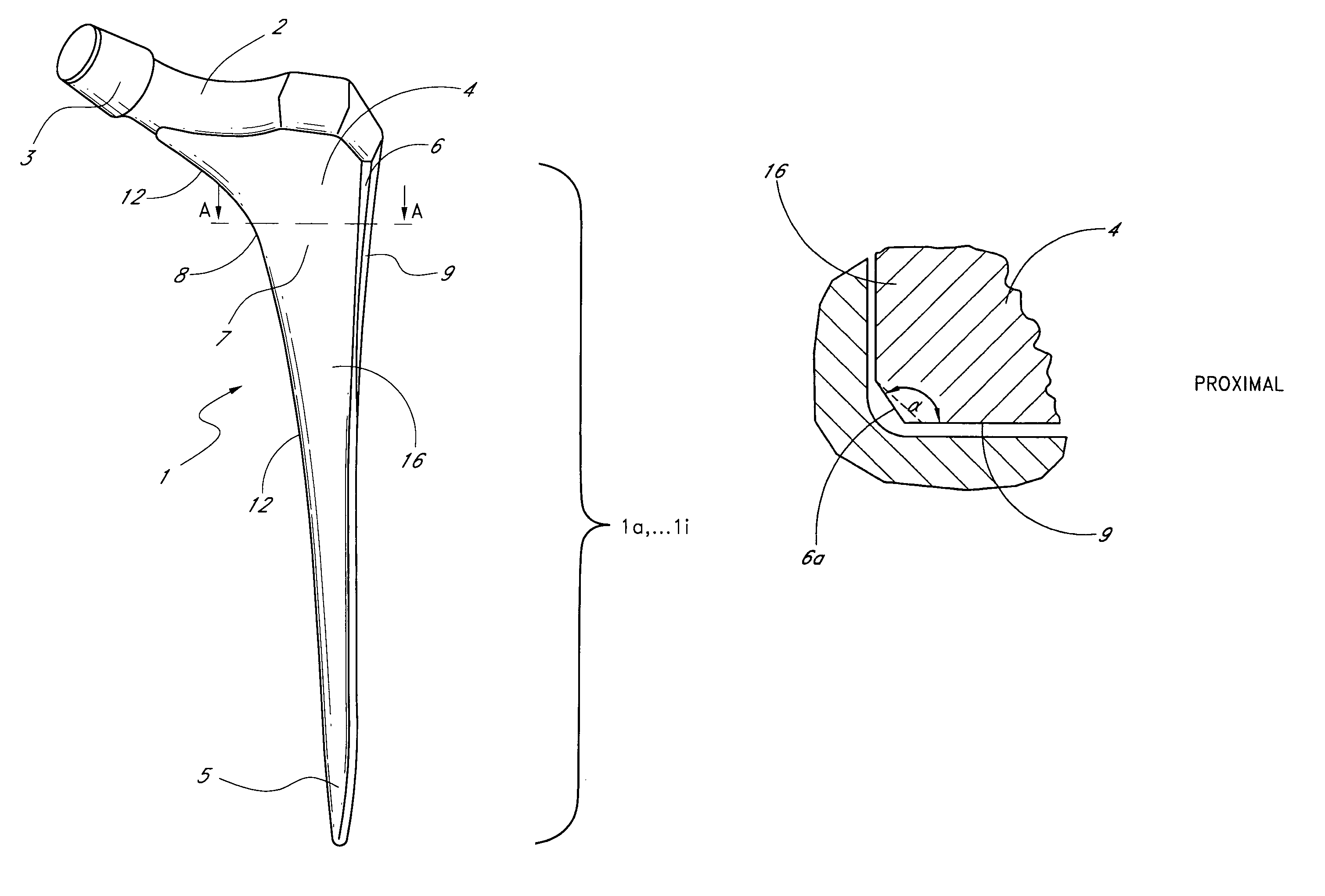
[0024]FIG. 1 gives a perspective view of an exemplary embodiment of a profiled shaft in which the characteristics according to the present invention are implemented. The profiled shaft shown here is in general designated by 1 and comprises a lower, distal, narrow end 5 and a section 7 that expands upward and in its upper end region is continuous with a fixation section 2, the latter in turn being continuous with a section 3 in the shape of a truncated cone that serves for the fixation of a spherical joint head. On the medial narrow side 12 in the proximal region the shaft has the form of a continuously bending curve 8, which ultimately ends in the region of the fixation section 2.

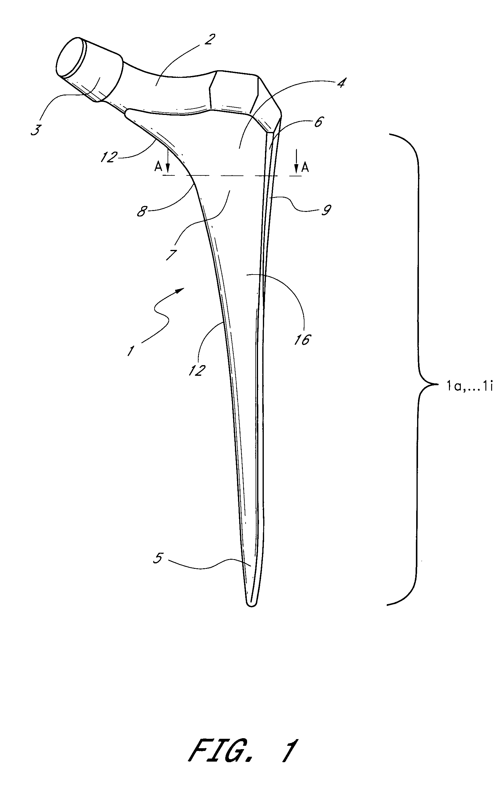
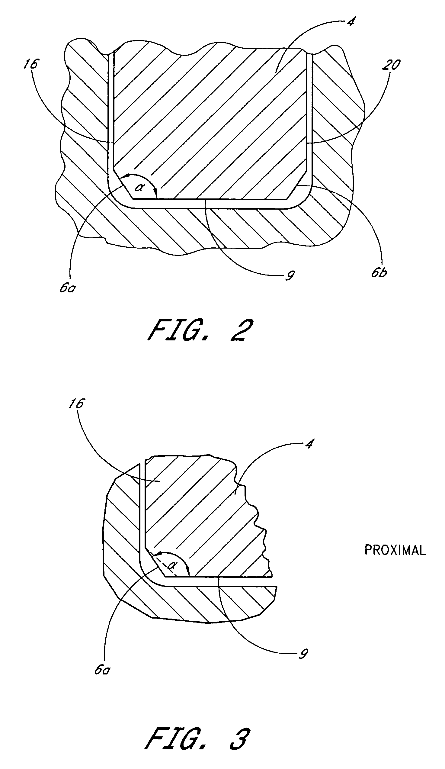
[0025]On the lateral side (anterior broad side 16) the shaft section merges in its proximal region with a trochanter wing 4. on which beveled corner surfaces 6 (facets) are formed. The anterior broad side 16 is substantially parallel to a posterior broad side 20 (FIG. 2).

[0026]In the conventional constructi...


PUM


Abstract

A profiled shaft for anchoring a hip-joint prosthesis in the femur is disclosed, with a shaft section and a fixation section that is formed at the end of the shaft section and that serves for the fixation of a spherical joint head, wherein the shaft section on the lateral surface in the proximal region merges with a trochanter wing at the edges of which beveled surfaces are formed. The essential point of the invention is that the angle formed between the plane of a beveled surface the plane of the adjacent surface is smaller than 135° and larger than 90°. In a construction of this kind the advantage of an improved filling of the empty space in the trochanter-wing region is achieved.

Description

CROSS REFERENCE TO RELATED APPLICATIONS[0001]This is a continuation of U.S. patent application Ser. No. 09 / 548,576, filed on Apr. 13, 2000, now U.S. Pat. No. 6,613,094, the entire contents of which are incorporated herein by reference. This application also relates to and claims foreign priority to German Patent Application No. 199 16 630.17, filed Apr. 13, 1999.BACKGROUND OF THE INVENTION[0002]1. Field of the Invention[0003]The invention relates to a profiled shaft for anchoring a hip-joint prosthesis in the femur, with a shaft section and a fixation section, formed at the end of the shaft section, which serves for the fixation of a spherical joint head, wherein the medial narrow side of the shaft section merges with a continuously curved arch that ends in the region of the fixation section, and wherein the lateral side of the shaft section in its proximal region merges with a trochanter wing on which the corners are beveled to form slanted surfaces (facets).[0004]2. Description of...

Claims


Application Information

Patent Timeline
Patent Type & Authority Patents(United States)
IPC IPC(8): A61F2/36A61F2/00
CPCA61F2/367A61F2/36A61F2/3662A61F2/3676A61F2002/30112A61F2002/30138A61F2230/0067A61F2002/30332A61F2002/3625A61F2002/365A61F2220/0033A61F2230/0004A61F2230/0017A61F2002/30205
Inventor ZWEYMULLER, KARL
Owner PLUS ORTHOPEDICS
Why Eureka
Try Eureka