Automatic cleaning assembly for a toilet bowl

a technology of automatic cleaning and toilet bowl, which is applied in water installations, lavatory sanitory, construction, etc., can solve the problems of limited time, time delay, and certain chemicals contained in cleaning agents that may have adverse effects on certain parts of toilet water holding tanks, and achieve low liquid flow rate and low flow rate

Inactive Publication Date: 2006-03-07
SIM JAE K
View PDF11 Cites 27 Cited by
  • Summary
  • Abstract
  • Description
  • Claims
  • Application Information

AI Technical Summary

Benefits of technology

[0011]Provided is a hydraulic time release system for delaying the flow of liquid therethrough in order to provide a delay of a release of cleaning agent for maintaining a level of cleanliness in an automatic cleaning assembly for a toilet or a urinal. The hydraulic time release system includes a timer body and is configured such that liquid entering the time release system at a timer inlet flow rate must substantially fill the timer body before the liquid exits the timer body at a flow rate that is substantially equivalent to the timer inlet flow rate. Such delay in the release of liquid from the timer body in turn causes a delay in the release of a solution of cleaning agent from the automatic cleaning system to the toilet bowl in order to ensure that cleaning agent solution remains in the bowl after each flushing cycle.
[0013]The first reservoir, second reservoir, and third reservoirs are each in at least partial fluid communication with another and with the float reservoir. The first reservoir is separated from the second reservoir by a first partition. The third reservoir is separated from the second reservoir by a second partition. The timer outlet is disposed in an exterior wall of the timer body at a location adjacent to the second reservoir. The first partition and second partition define the second reservoir. The first partition is configured to prevent rapid draining of the first reservoir during siphoning action created by flushing of the toilet so that a certain amount of liquid remains in the first reservoir after flushing. The second partition is configured to prevent draining of the second reservoir through a bleed valve that is located within the third reservoir so that, after each flush, the liquid remaining in the first reservoir flows into the second reservoir through a passageway.
[0014]The passageway, located at a lower portion of the first partition, allows liquid to flow from the first reservoir into the second reservoir at a relatively low flow rate. The passageway is sized and configured such that the rate at which liquid passes from the first reservoir to the second reservoir is less than the rate at which cleaning agent solution is released from the cleaning assembly. Such release of cleaning agent solution occurs during each flush of the toilet. Due to the relatively low liquid flow rate from the first reservoir to the second reservoir, the siphoning effect caused by flushing (and which would otherwise drain the timer body) ceases prior to completion of the draining of the first reservoir into the second reservoir. In this manner, liquid entering the second reservoir will rise to a level above that of the timer outlet such that the timer outlet remains submerged in liquid after each flush cycle. Because the timer outlet is submerged, cleaning agent gases that are generated within the cleaning assembly are prevented from flowing back into the timer body wherein the gas may otherwise be released to the environment through the check valve.

Problems solved by technology

When connected to the cleaning assembly, the time release system provides a time delay in the release of cleaning agent from the cleaning assembly such that the cleaning agent is retained within the toilet bowl after flushing of the toilet.
Unfortunately, such a system only allows for a limited time during which the cleaning agent is actually in contact with the toilet bowl because the toilet bowl eventually drains to the sewer and is refilled with water that does not contain any cleaning agent.
Another drawback associated with systems comprising cleaning agent tablets or blocks is that certain chemicals contained within the cleaning agent may have an adverse effect on certain parts of the toilet water holding tank.
More specifically, non-metallic parts such as rubber or plastic parts contained within the toilet water holding tank may be subject to attack by chemicals of the cleaning agent.
Over time, the proper sealing and function of such nonmetallic plastic and rubber parts may be compromised and may ultimately have an adverse effect on the proper operation of the toilet.
A further drawback associated with cleaning agents in the form of tablets or blocks is that because the cleaning agent is always submerged within the toilet water holding tank, the useful life of the cleaning agent is relatively short such that the cleaning agent tablets or blocks must be periodically replaced.
Unfortunately, the cleaning agent solution only contacts inner surfaces of the toilet bowl for a very short period of time during the initial stages of the flushing of the toilet.
Unfortunately, only a diluted mixture of cleaning agent solution remains in the toilet bowl which reduces the overall effectiveness of the cleaning agent in maintaining the cleanliness of the toilet bowl.

Method used


Image

  • Automatic cleaning assembly for a toilet bowl
  • Automatic cleaning assembly for a toilet bowl
  • Automatic cleaning assembly for a toilet bowl

Examples


Embodiment Construction

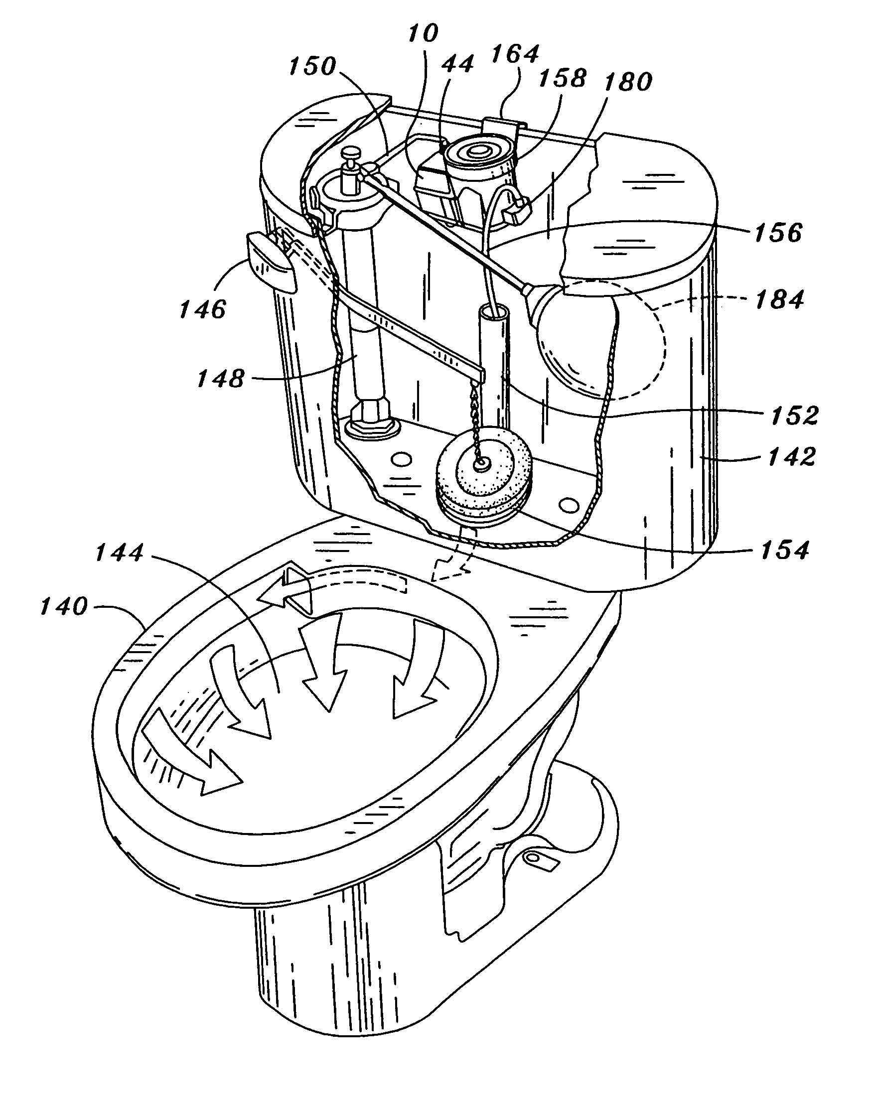
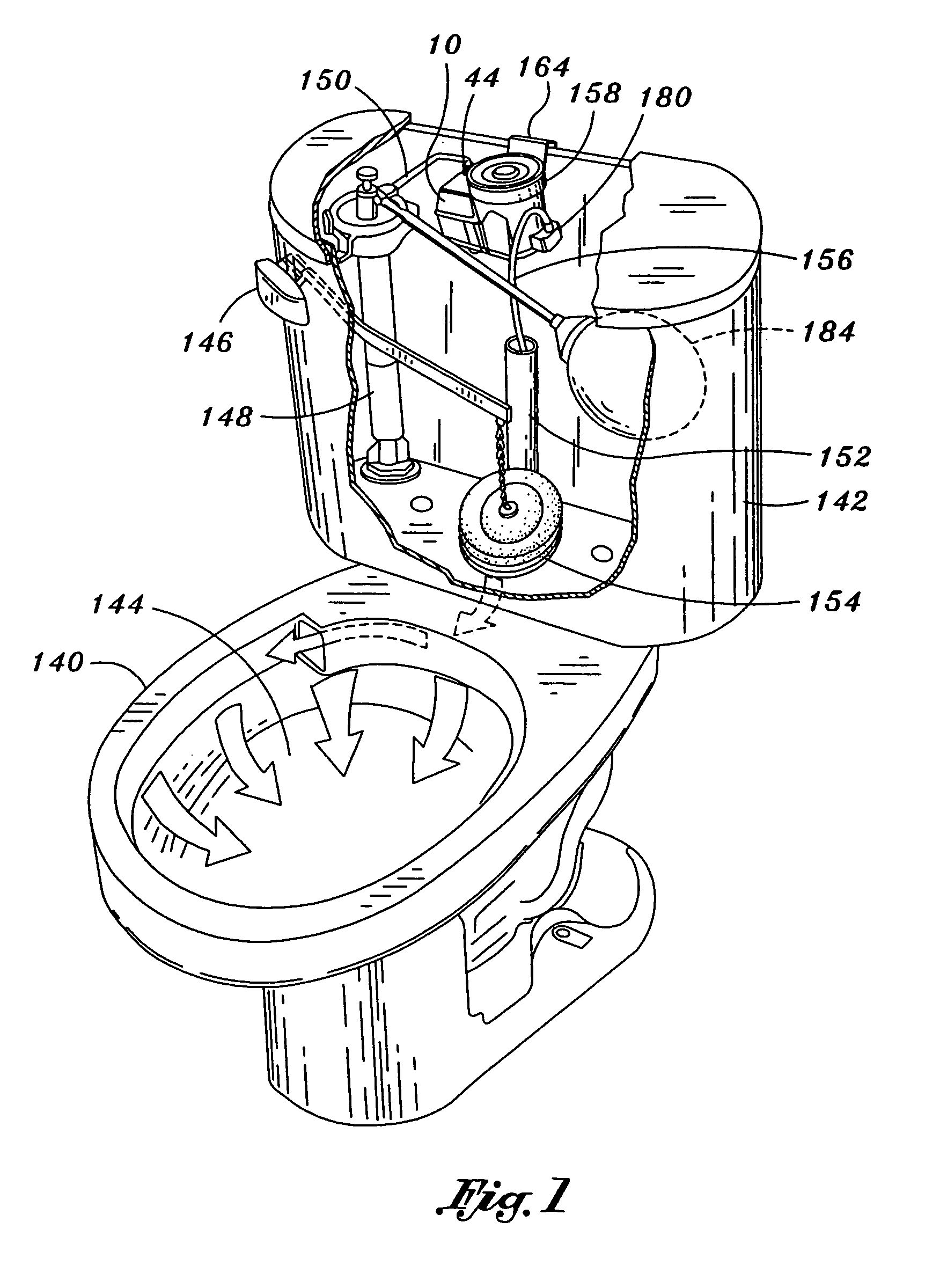
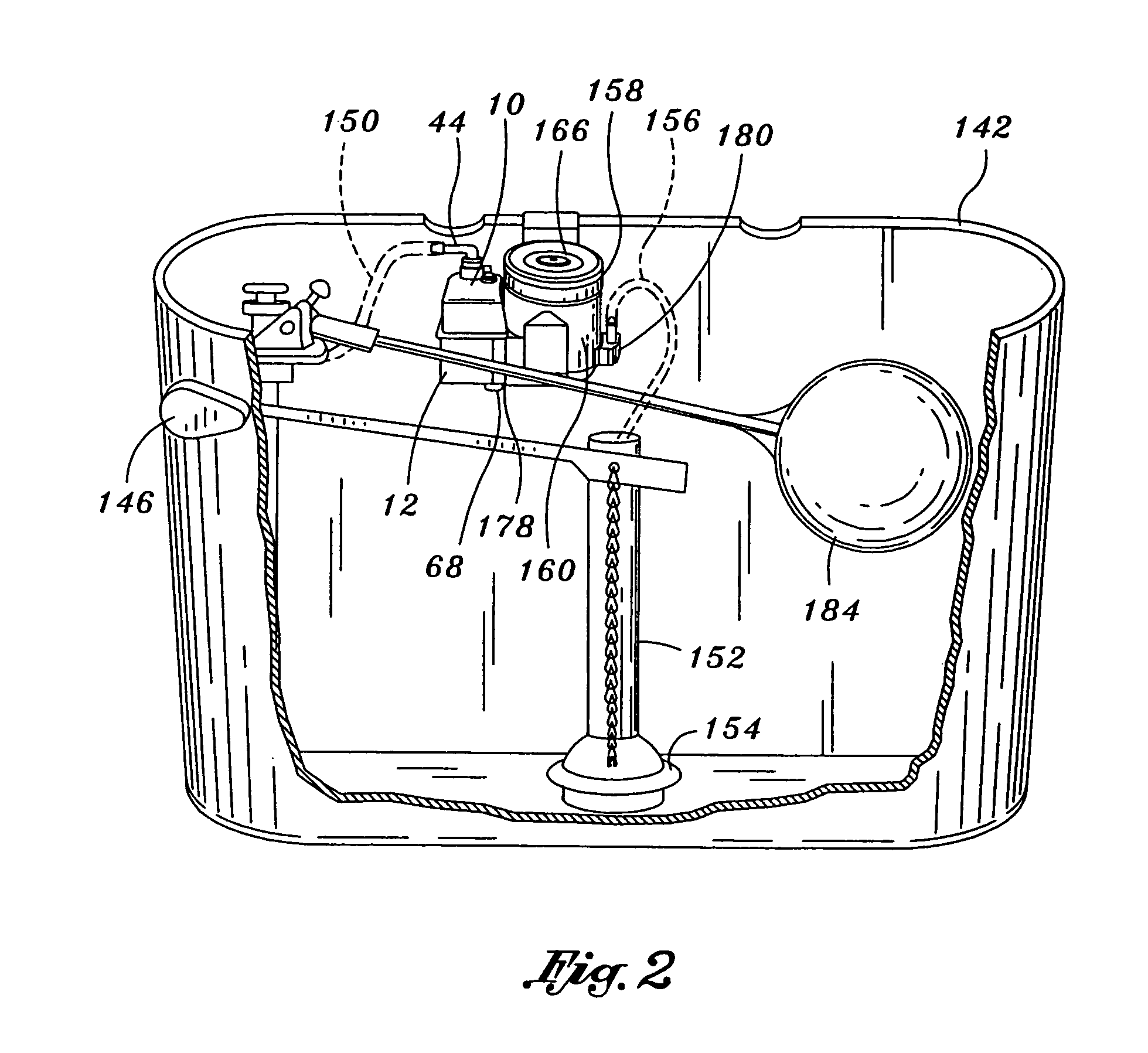
[0029]Referring now to the drawings wherein the showings are for purposes of illustrating various aspects of the invention and not for purposes of limiting the same, provided is a uniquely configured hydraulic time release system 10 specifically adapted for regulating the flow of liquid therethrough and which is operative to provide a time delay for the release of cleaning agent 174 such as may be used in an automatic cleaning assembly 158 for a toilet 140 or a urinal. The time release system 10 may be specifically adapted to be connectable to the automatic cleaning system 158 although it is contemplated that the time release system 10 may be used in conjunction with other fluidic devices requiring a delay in the release of fluid therefrom.

[0030]Referring now to FIGS. 1–12, shown is the hydraulic time release system 10 of the present invention as may be connectable to the automatic cleaning assembly 158 and which may be installed within a toilet water holding tank 142 of the toilet ...


PUM


Abstract

Provided is a hydraulic time release system for regulating the flow of liquid therethrough. The time release system comprises a timer body having a timer inlet for providing liquid at a timer inlet flow rate and a timer outlet for discharging liquid at a timer outlet flow rate. The timer body is divided into a first reservoir, a second reservoir, a third reservoir and a float reservoir. The first reservoir includes a catch pan mounted on an open drain tube that is positioned below the timer inlet. The first, second and third reservoirs are in at least partial fluid communication with the float reservoir. A timer float assembly is moveable between open and closed positions in response to variations in the float reservoir liquid level. The closed position is such that the flow of liquid into the drain tube is blocked causing the timer body to fill with liquid whereupon the timer outlet flow rate is substantially equivalent to the timer inlet flow rate.

Description

CROSS-REFERENCE TO RELATED APPLICATIONS[0001]The present application is a continuation of U.S. application Ser. No. 11 / 042,267 entitled AUTOMATIC CLEANING ASSEMBLY FOR A TOILET BOWL filed Jan. 25, 2005, now U.S. Pat. No. 6,944,890.STATEMENT RE: FEDERALLY SPONSORED RESEARCH / DEVELOPMENT[0002]Not ApplicableBACKGROUND OF THE INVENTION[0003]The present invention relates to a hydraulic timer mechanism and, more particularly, to a hydraulic time release system that is specifically adapted for delaying the flow of liquid therethrough. In addition, the hydraulic time release system is adapted for use with a cleaning assembly that may be attached to an inside wall of a toilet water holding tank of a toilet or urinal. When connected to the cleaning assembly, the time release system provides a time delay in the release of cleaning agent from the cleaning assembly such that the cleaning agent is retained within the toilet bowl after flushing of the toilet.[0004]Included in the prior art are seve...

Claims


Application Information

Patent Timeline
Patent Type & Authority Patents(United States)
IPC IPC(8): E03D9/00E03D9/03
CPCE03D9/037
Inventor SIM, JAE K.
Owner SIM JAE K
Why Eureka
Try Eureka