Apparatus for and method of adjusting a switching regulator output for a circuit having a pre-charge voltage

a technology of switching regulator and output, which is applied in the direction of electric variable regulation, process and machine control, instruments, etc., can solve the problems of difficult to accurately detect reverse current and the circuit of fig. 1 may complicate an integrated circui

Inactive Publication Date: 2005-07-26
EXAR CORP
View PDF7 Cites 20 Cited by
  • Summary
  • Abstract
  • Description
  • Claims
  • Application Information

AI Technical Summary

Benefits of technology

[0007]Preventing a pre-charge voltage at a switching regulator output terminal from being drained when a switching regulator is turned on, is most effectively accomplished when the regulator switched node is not connected to ground until the target voltage is greater than the pre-charge voltage. It is also advantageous to combine a soft start adjustment of a switching regulator target voltage with a circuit that prevents a pre-charge voltage from being drained.

Problems solved by technology

This condition is especially problematic for switching regulators that employ a soft start, i.e, gradually increase a target regulator output voltage at startup.
Consequently, it is difficult to accurately detect reverse current.
Additionally, the circuit of FIG. 1 may complicate an integrated circuit comprising switching regulator 9 because the circuit requires an additional pin to provide access to switched node 30.

Method used


Image

  • Apparatus for and method of adjusting a switching regulator output for a circuit having a pre-charge voltage
  • Apparatus for and method of adjusting a switching regulator output for a circuit having a pre-charge voltage
  • Apparatus for and method of adjusting a switching regulator output for a circuit having a pre-charge voltage

Examples


Embodiment Construction

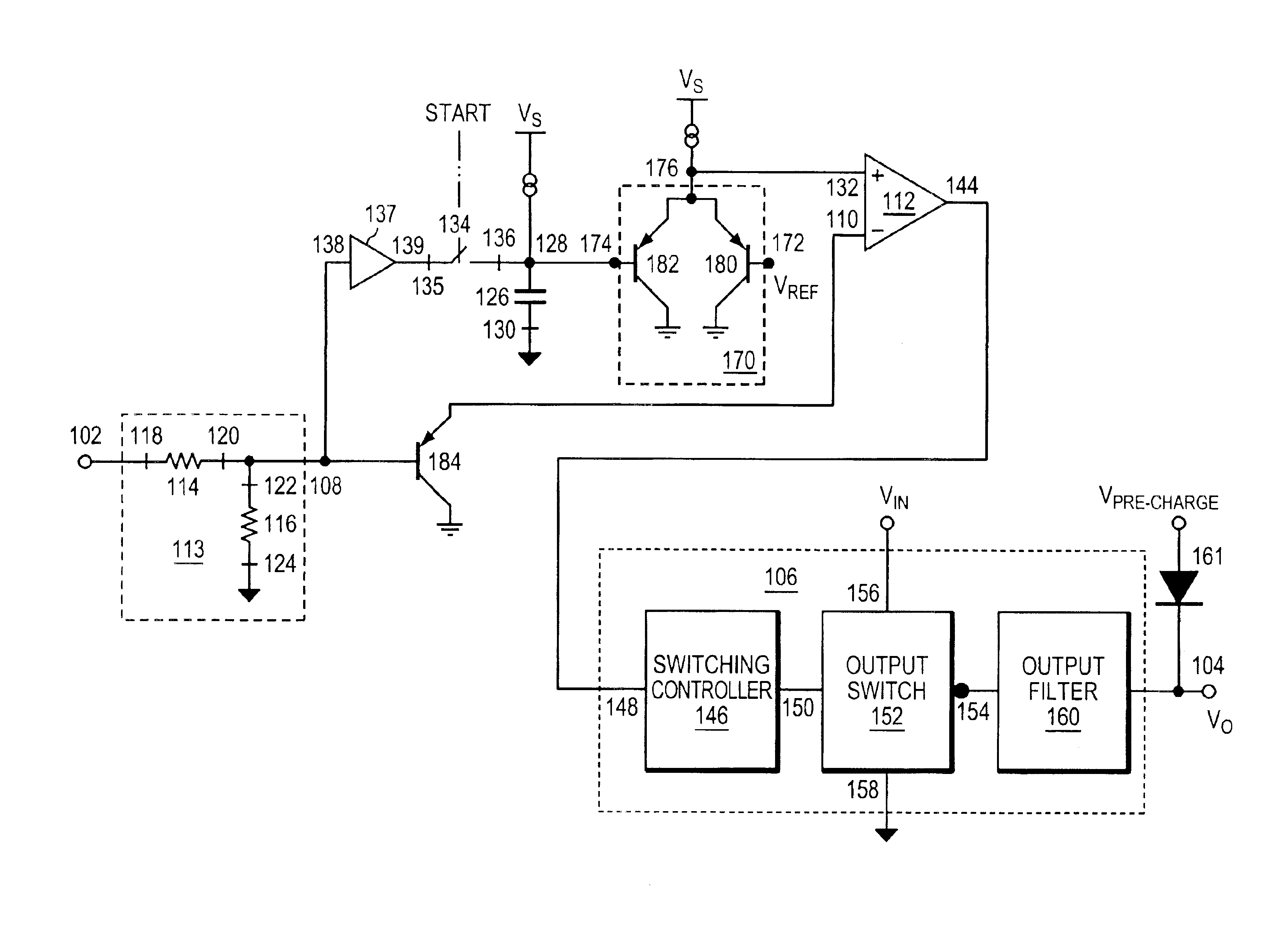
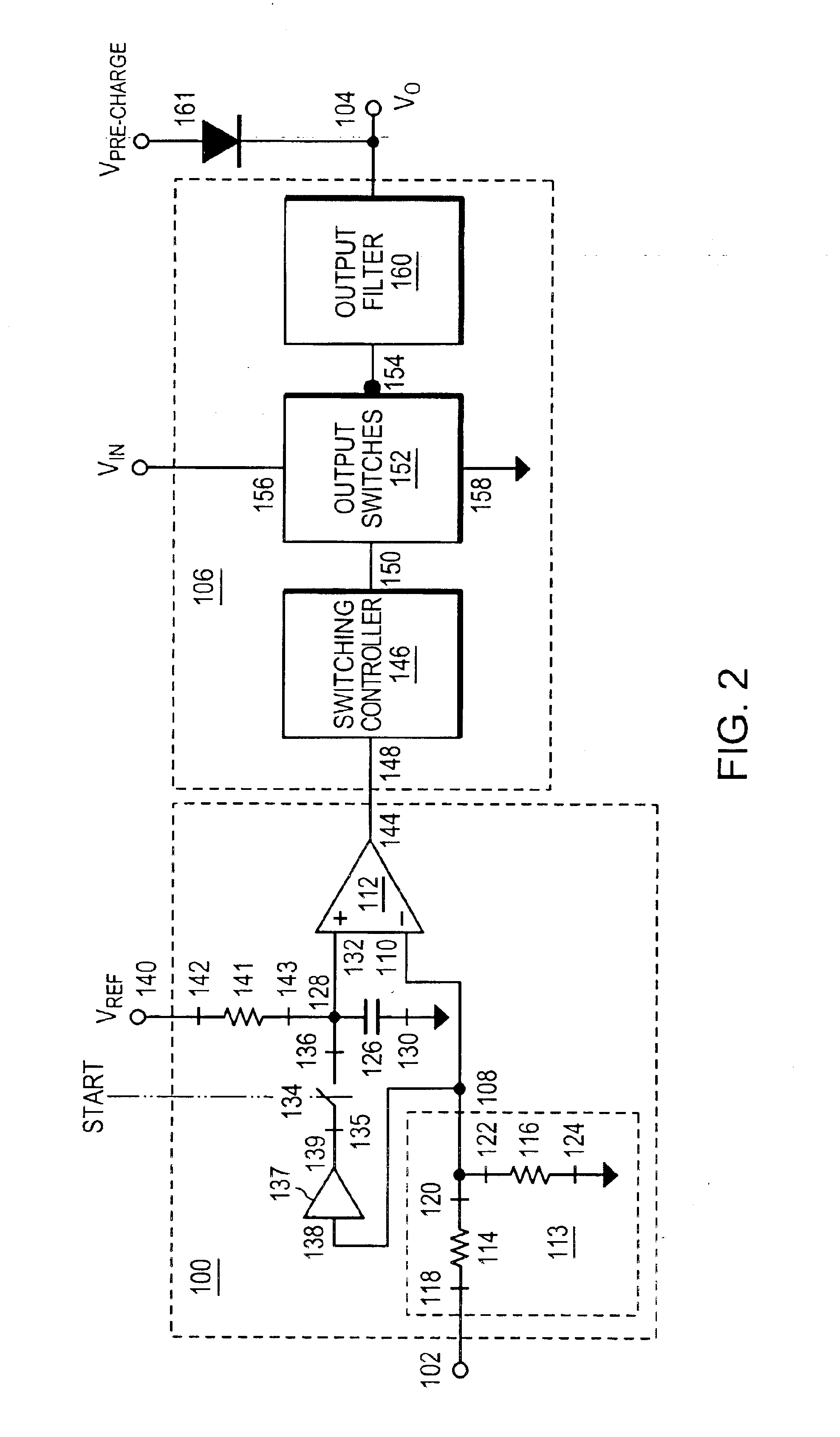
[0021]Referring now to FIG. 2, one embodiment of a control circuit 100 that is employed with a switching regulator 106 is shown. Control circuit 100 is, in part, used to prevent the discharge of a pre-existing voltage present at a regulator output terminal 104. The control circuit 100 input is connected to the regulator output terminal 104 at a feedback terminal 102 through a means not shown here. Control circuit 100 includes an error amplifier 112 that has an output terminal 144 that is also the output of control circuit 100. Error amplifier output terminal 144 is connected to the input of switching regulator 106. The comparison signal provided by error amplifier 112 at error amplifier output terminal 144 is employed by the switching regulator 106 to control the regulator output voltage. In one embodiment, the comparison is performed by a comparator that provides a logic signal at its output terminal. In one embodiment, switching regulator 106 includes a switching controller 146, o...


PUM


Abstract

A switching regulator target voltage is adjusted to a first value corresponding to a pre-charge voltage that is present at a regulator output terminal. The switching regulator responds to a comparison signal resulting from a comparison of the target voltage and a feedback voltage. When the switching regulator is on, the target voltage is adjusted to a second value corresponding to a nominal regulator output voltage. In one embodiment, a synchronous switch is disabled when a lockout circuit receives a disable signal. The lockout circuit is unlocked when an enable signal is provided by a switching controller.

Description

FIELD OF THE INVENTION[0001]The invention relates to the field of switching regulators, and in particular, to adjusting a switching regulator output when the regulator is turned on.BACKGROUND OF THE INVENTION[0002]Generally, switching regulators are employed as DC power sources. In some applications, when the regulator is first turned on, a pre-existing voltage exists at the switching regulator output terminal, e.g., a pre-charge voltage. This pre-charge voltage may either result from an external voltage source, or a residual charge that exists across the load, for example, a residual voltage across output filter capacitors of the switching regulator. Many switching regulators employ output switches that alternately connect a switched node to an input voltage and ground when the switching regulator is on. Often, these output switches are solid state devices (e.g., MOSFETs) that allow current to flow through the switch in either direction from a switch drain terminal to a switch sour...

Claims


Application Information

Patent Timeline
Patent Type & Authority Patents(United States)
IPC IPC(8): H02M1/00H02M3/158H02M3/04H02M1/36
CPCH02M1/36H02M3/1588H02M2001/0025Y02B70/1466H02M1/0025Y02B70/10
Inventor GODER, DIMITRYSANZO, CHRISTOPHER J.
Owner EXAR CORP
Why Eureka
Try Eureka