Imaging forming apparatus

a technology of image forming apparatus and forming apparatus, which is applied in the direction of electrographic process apparatus, instruments, optics, etc., can solve the problems of affecting the transfer operation of the other body, so as to prevent such interference, improve productivity, and improve productivity.

Inactive Publication Date: 2006-03-07
CANON KK
View PDF14 Cites 6 Cited by
  • Summary
  • Abstract
  • Description
  • Claims
  • Application Information

AI Technical Summary

Benefits of technology

[0007]This invention is to prevent such interference from occurring at the transfer operation. This invention, particularly for an image forming apparatus equipped with plural image carriers as image carrying means in aiming at improvements in productivity, is to solve the above problems without reducing the productivity.

Problems solved by technology

With this apparatus, however, image formation requires two rotations of the intermediate transfer body, and the following problems may be raised where images are successively formed on plural sheets.
There may raise a problem that both transfer operations are interfering with each other where the fourth color toner image of a previous image is transferred from one photosensitive body to an intermediate transfer body and at the same time the first color toner image of the subsequent image is transferred from the other photosensitive body to the intermediate transfer body.
That is, the transfer operation of one body may affect the transfer operation of the other body.
With this interference at the transfer operation, transfer defects may occur.

Method used


Image

  • Imaging forming apparatus
  • Imaging forming apparatus
  • Imaging forming apparatus

Examples


first embodiment

[First Embodiment]

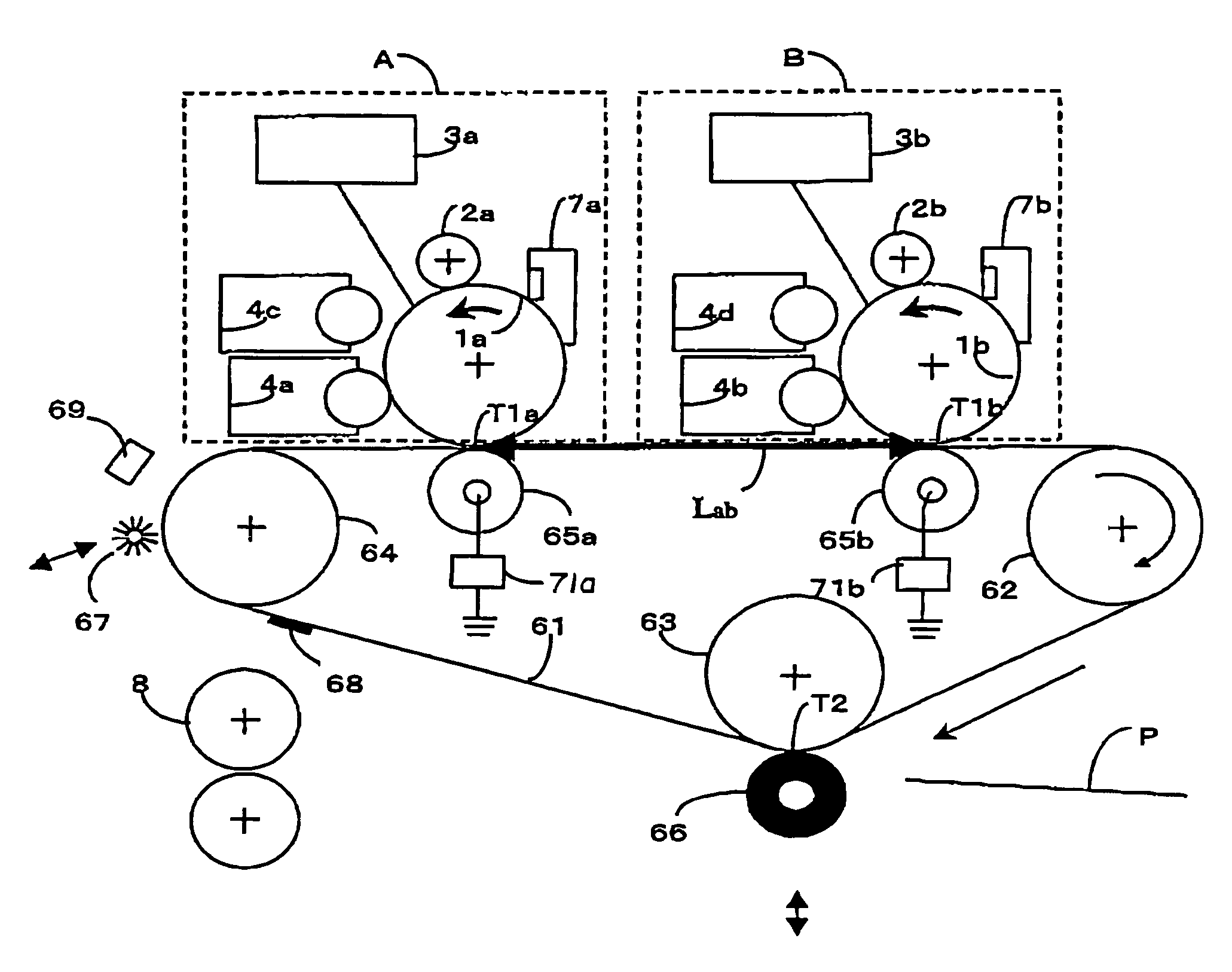
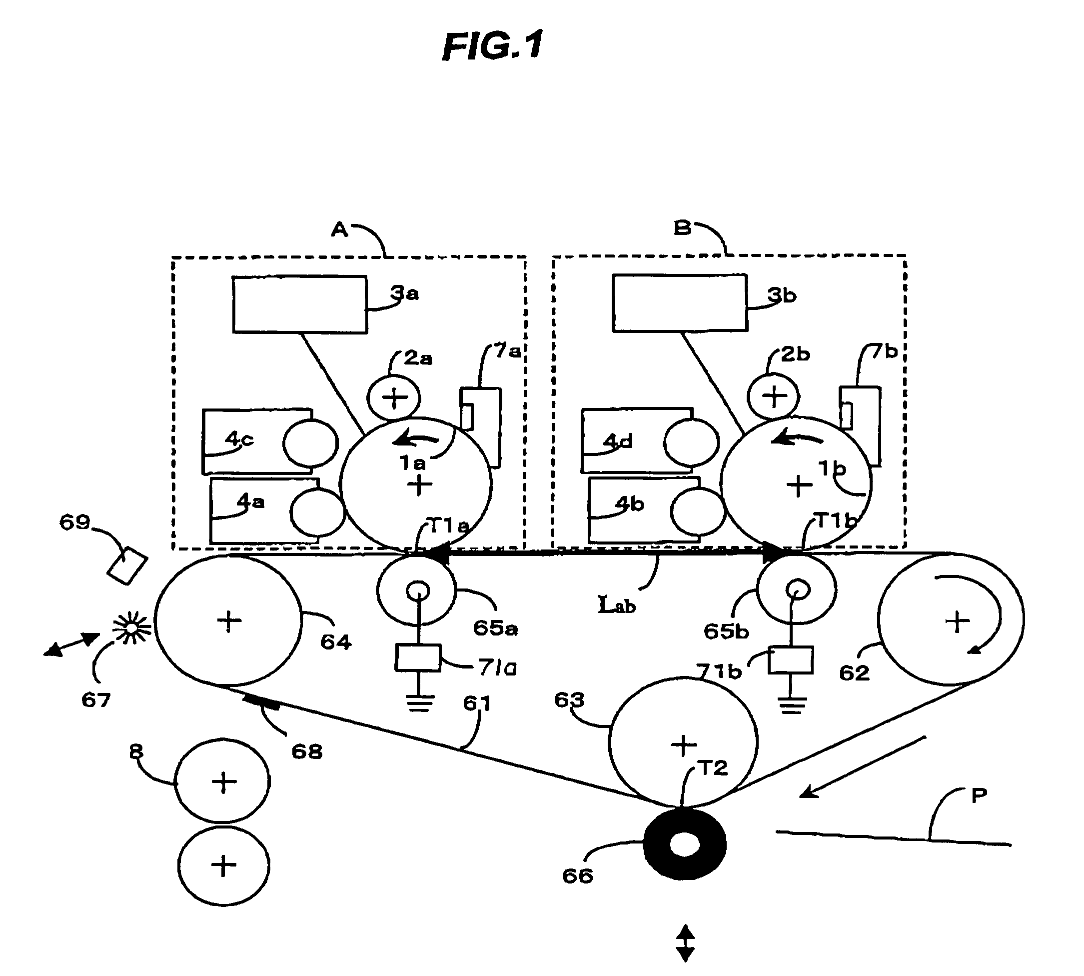
[0027]FIG. 1 is for a first embodiment of the invention. The embodiment is described with reference to the drawings.

[0028]Around an intermediate transfer belt 61, disposed are a first image production section A and a second image production section B, each of which is constituted of a photosensitive drum, a charging device, a charging roller, two switchable developing devices, and a cleaning device.

[0029]In the first image production section A, the photosensitive drum 1a is charged with the charging roller 2a, and the exposing device 3a exposes images of the first color yellow. The latent image formed on the photosensitive drum 1a is developed by the developing device 4a corresponding to the first color yellow. It is to be noted that the developing devices 4a, 4c are interchangeably used according to a drive means not shown. The developed yellow toner image is transferred to an intermediate transfer belt 61 by a primary transfer roller 65a (at a first transfer posi...

second embodiment

[Second Embodiment]

[0047]In the first embodiment, the apparatus is structured so that Lr−Lm >Lab . . . (1) is satisfied to prevent the transfer biases applied to the primary transfer rollers 65a, 65b from interfering with each other.

[0048]Meanwhile, in a case that the relations among the Lr, the Lm, and the Lab, are:

Lr−Lm≦Lab  (2),

the following is a method for preventing the primary transfer biases from interfering with each other. As described in the first embodiment, as a method to match and overlap the position of the toner images of the respective colors on the intermediate transfer belt 61, a mark 68 formed on the intermediate transfer belt 61 is read out by an optical sensor 69, and the read signal I-top (Image top) is made as reference, thereby writing the respective images on the photosensitive drums 1a, 1b after the prescribed timings.

[0049]In this embodiment, the timing from reception of the I-top signal to actual image exposure by laser beam on the photosensitive drums 1a...

third embodiment

[Third Embodiment]

[0052]Next, a situation that the transfer material most frequently used and the transfer material larger than the material, both are used as described in the first embodiment, is described.

[0053]With respect to the transfer material most frequently used, as described in the first embodiment, the apparatus is structured as Formula (1) is satisfied, and during the successive printing operation, the image area is always set at the same position on the intermediate transfer belt 61. In other words, where the time needed for one rotation of the intermediate transfer belt 61 is set as T, the interval of the respective printing during the successive printing operation is desirably set as T, and with respect to the transfer materials larger than that material, it is designed so that Formula (2) and Formula (3) are satisfied and that the image area is shifted downward on the intermediate transfer belt 61 according to the printing sheet number.

[0054]With this control, the pr...


PUM


Abstract

An image forming apparatus includes an image carrying member and an intermediate transfer body in an endless shape movable and receivable of toner images from said image carrying member at first and second transfer positions. The following relationship is satisfied where a distance from the first transfer position to the second transfer position along the moving direction of the intermediate transfer body is denoted as Lab, a circumference of the intermediate transfer in the moving direction is denoted as Lr, and a length of the toner image formed on the intermediate transfer body is denoted as Lm−Lr−Lm>Lab.

Description

BACKGROUND OF THE INVENTION[0001](a) Field of the Invention[0002]This invention relates to an image forming apparatus such as a printer, a photocopier, and a facsimile machine and, more particularly, to an apparatus utilizing an intermediate transfer body.[0003](b) Description of Related Art[0004]As image forming apparatuses of a full-color electrophotographic method, an apparatus has been known in which plural toner images are sequentially formed on a single photosensitive body and are overlapped on an intermediate transfer body to form full color images. More specifically, the apparatus is described with reference to FIG. 5. Developing devices 4a, 4b, 4c, 4d having respective toners of different colors are sequentially arranged as to face to an image carrying means 1 as a single photosensitive drum, thereby sequentially forming the toner images of the respective colors. The toner images of the respective colors are sequentially overlapped onto the intermediate transfer body 61 fro...

Claims


Application Information

Patent Timeline
Patent Type & Authority Patents(United States)
IPC IPC(8): G03G15/01G03G15/16
CPCG03G15/0131G03G15/0121G03G15/0184G03G2215/0106G03G15/0173
Inventor TAKEUCHI, AKIHIKOKOBAYASHI, TATSUYAENOMOTO, NAOKISUZUKI, TAKEHIKOSODA, TAKAMITSU
Owner CANON KK
Why Eureka
Try Eureka