
Trigger system and method of installing same

a technology of trigger system and trigger bar, which is applied in the direction of firing/triggering mechanism, weapons, ammunition loading, etc., can solve the problems of cumbersome approach and improve the effect of the

Inactive Publication Date: 2006-03-14
WILSONS GUN SHOP
View PDF12 Cites 9 Cited by
  • Summary
  • Abstract
  • Description
  • Claims
  • Application Information

AI Technical Summary

Benefits of technology

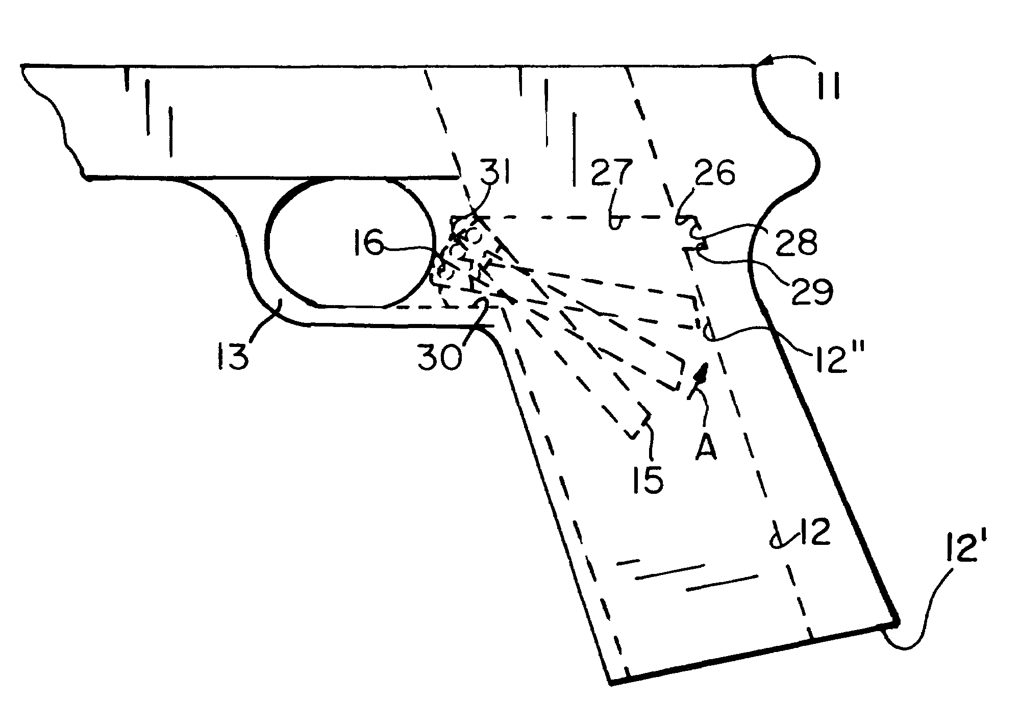
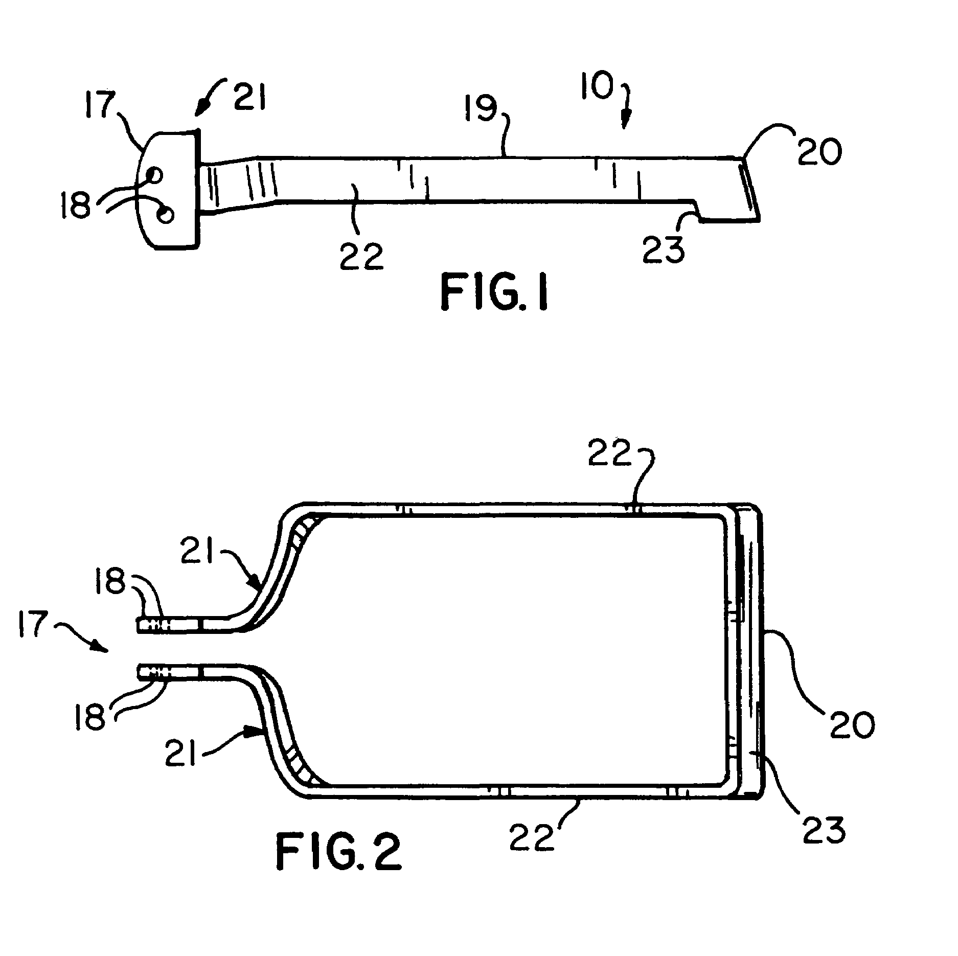
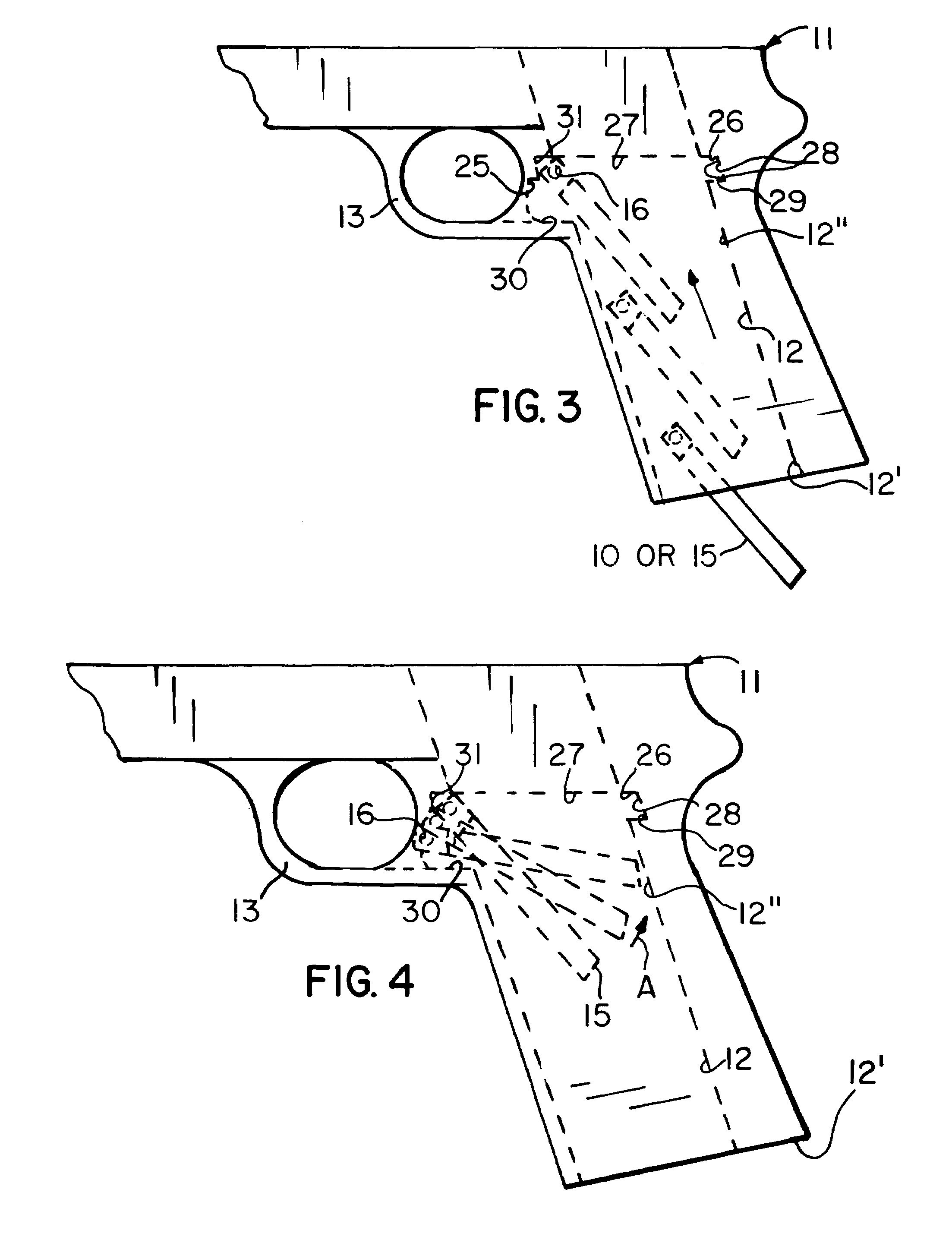
[0008]There is also a frame for an automatic handgun comprising a magazine well having a lower inlet opening for receiving a magazine and an upper outlet opening, an interior space communicating with the upper outlet opening for the placement and carrying of a trigger and trigger bar in the space in a manner to provide for cooperative engagement between a trigger and trigger bar and a firing apparatus for a handgun, the interior space being defined by a front cavity including a pair of spaced apart lower shoulders and a pair of spaced apart upper shoulders for limiting movement of a trigger bar forwardly and upwardly respectively in the space during installation of a trigger bar by movement upwardly in the well. The interior space is further defined by a rear cavity, the rear cavity including a pair of spaced apart lower ledges and a pair of spaced apart rear walls for limiting rearward travel of a trigger bar, the magazine well being sized to provide for installation of a trigger bar into the interior space through the inlet opening and through the outlet opening of the magazine well. The interior space is further defined by a pair of spaced apart shoulders extending from a respective upper shoulder in the front cavity to a respective rear wall for limiting upward movement of a trigger bar.

Problems solved by technology

This approach is cumbersome and improvements are therefore needed.

Method used


Image

  • Trigger system and method of installing same
  • Trigger system and method of installing same
  • Trigger system and method of installing same

Examples


Embodiment Construction

[0014]Introduction

[0015]The original colt 1911 style staggered stack magazine pistol frame made allowance for the trigger and trigger bar to be assembled as a single unit and to be placed into the frame from the rear of the frame.

[0016]In order to allow this and because the trigger bar passed on either side of the magazine of the pistol slots were cut into the frame on either side of the magazine well and this area was then covered at the rear by the pistols' grip safety, which is a separate entity.

[0017]Since the original Colt 1911 frame was designed a number of modifications were made whereby, a larger magazine capacity was attained by enlarging the magazine well and using a double stack or staggered stack magazine. Because of the increased width of the magazine the trigger bar also had to be made wider and therefore the normal standard colt style grip safety would not cover the area of the slots in the side of the magazine well. It was therefore necessary to put wings onto the si...


PUM


Abstract

A trigger system for an automatic handgun includes a trigger bar sized to be installed in an interior space behind a trigger by movement from the magazine well. The trigger bar is first inserted into the inlet opening of the magazine well and into the interior space which includes a front cavity having a pair of spaced apart upper shoulders and lower shoulders that limit movement of the trigger bar upwardly and forwardly respectively. The interior space further includes a rear cavity that includes a pair of spaced apart lower ledges and a pair of spaced apart rear walls for limiting the rearward and downward movement of the trigger bar. The front cavity is adjacent the trigger and trigger guard. The rear cavity is formed within the handgrip. The trigger system and method is specifically designed for a Colt 1911 .45 pistol with an enlarged magazine well inlet opening for receiving an enlarged stagger magazine.

Description

CROSS REFERENCE TO RELATED APPLICATIONS[0001]Not Applicable.STATEMENT REGARDING FEDERALLY SPONSORED RESEARCH OR DEVELOPMENT[0002]Not Applicable.REFERENCE TO A MICROFICHE APPENDIX[0003]Not Applicable.BACKGROUND OF THE INVENTION[0004]The present invention relates to handgun trigger assemblies and particularly to the method of installation of a trigger and trigger bar.DESCRIPTION OF RELATED ART[0005]The original frame of the colt 1911 pistol utilizes a trigger and trigger bar that is assembled as a single unit and installed from the rear of the frame. Modifications have been made to the pistol to allow for the use of larger magazines with the result that further modifications had to be made to the standard grip safety. This approach is cumbersome and improvements are therefore needed.BRIEF SUMMARY OF THE INVENTION[0006]In one aspect of the present invention there is provided a method of installing a trigger bar in an automatic pistol having a magazine well for carrying a magazine and a...

Claims


Application Information

Patent Timeline
IPC IPC(8): F41A19/00
CPCF41A19/10
Inventor DU PLESSIS, ALEXANDER BENJAMIN
Owner WILSONS GUN SHOP
Learn More