
Eyeglass structures having mounting supports in temple members

a technology of eyeglasses and temple members, which is applied in the field of eyeglasses, can solve the problems of permanent creases, unfavorable wearers, and eyeglasses with creases on both sides of the nose, and achieve the effect of not affecting the wearer

Inactive Publication Date: 2006-03-14
KIM BYUNG SUK
View PDF2 Cites 23 Cited by
  • Summary
  • Abstract
  • Description
  • Claims
  • Application Information

AI Technical Summary

Benefits of technology

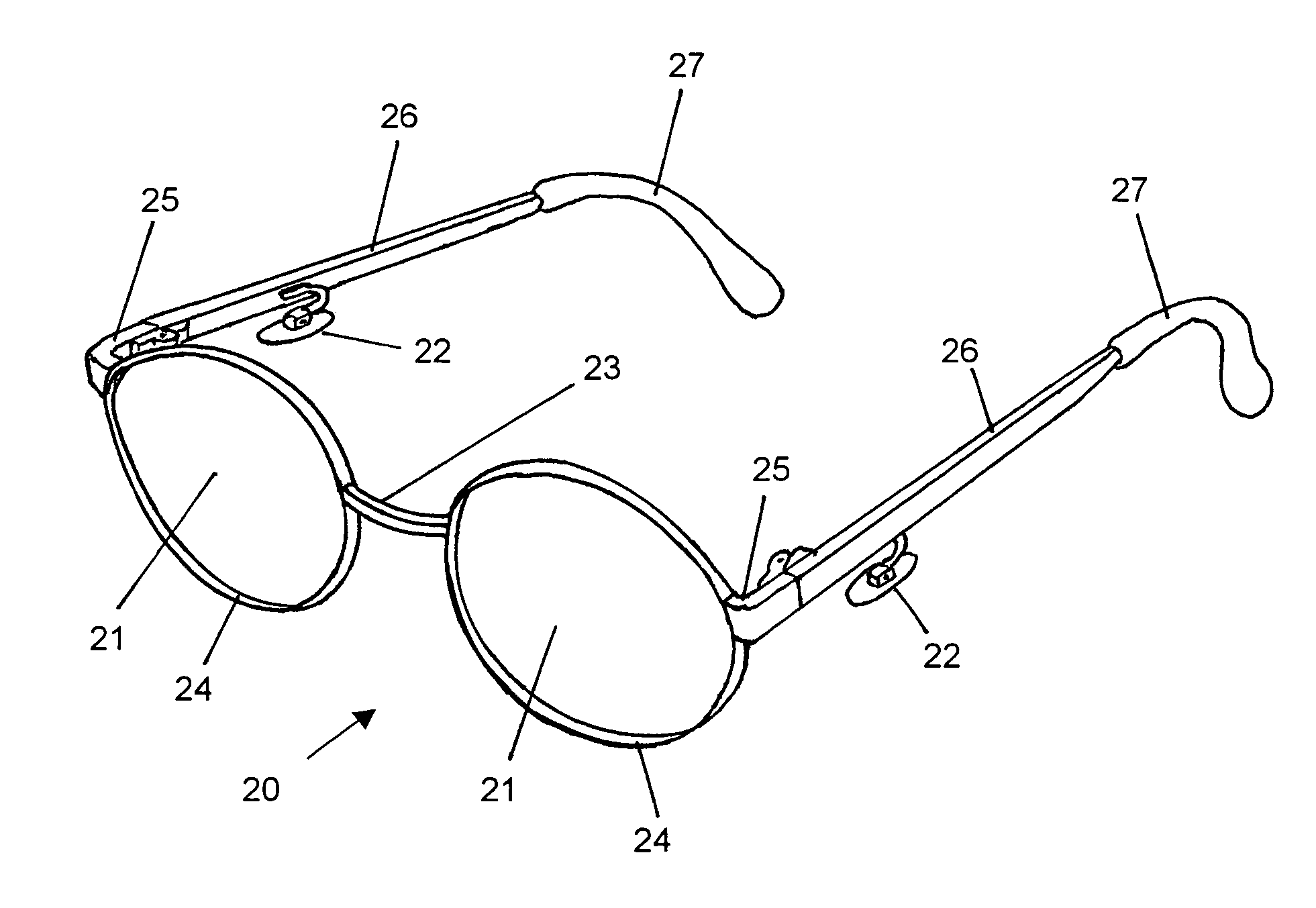
[0008]The principal object of the present invention is to provide an eyeglass structure that overcomes the aforementioned problems and that can be worn without discomfort while avoiding any contact with the nose of the wearer.

Problems solved by technology

Such eyeglass structures have the major portion of the weight thereof concentrated on the nose of the person wearing same and, therefore, tend to bear on and slide down the nose.
Constant wearing of these conventional eyeglass structures often results in unsightly creases in the skin and tissue on both sides of the nose.
This pressure on the sensitive part of the face can become irritating to the wearer and can even cause permanent creases in the areas of contact upon wearing of these conventional eyeglass structures over an extended period of time.
The pressures on both sides of the nose can also cause discomfort to the wearer, e.g., headaches, eye congestions, etc.
Traditional eyeglass structures can not be used by many people after nose surgery due to the pressures exerted by conventional frame members.
Also, some people have such nose shapes that are difficult and, in some instances, practically impossible to fit with conventional eyeglass structures that will remain in position thereon.
It is, of course, understood that a person who is handicapped due to the loss of a nose can not be accommodated by these conventional eyeglass structures.
These additional components may lead to an increase in the production cost of these special eyeglass structures.
Head-mount type eyeglass structures are large or have tight headbands or members extending over the top of the head are unsightly and the hairstyle of the wearer could be damaged badly.
While these eyeglass structures may be suitable for the purposes for which they were designed, still there is a need for eyeglass structures that utilize other area than the nose as a supporting base for the eyeglass structure and yet to suffice consumers in convenience, cost, and style.

Method used


Image

  • Eyeglass structures having mounting supports in temple members
  • Eyeglass structures having mounting supports in temple members
  • Eyeglass structures having mounting supports in temple members

Examples


Embodiment Construction

[0024]The following discussion describes in detail one embodiment of the invention and several variations of that embodiment. This discussion should not be construed, however, as limiting the invention to those particular embodiments because the disclosed embodiments are merely exemplary of the invention which may be embodied in various forms. Specific structural and functional details disclosed herein are not to be interpreted as limiting but merely as a basis for claims and as a representative basis for teaching one skilled in the art to employ the present invention in any detailed structure.

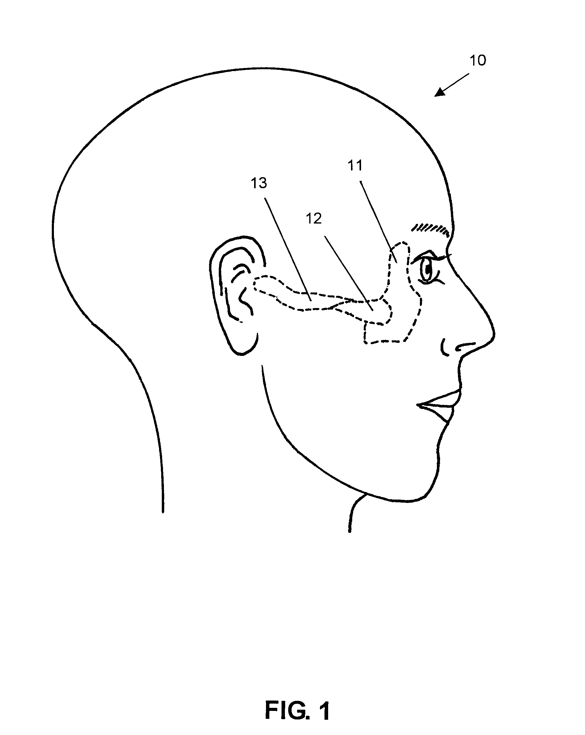
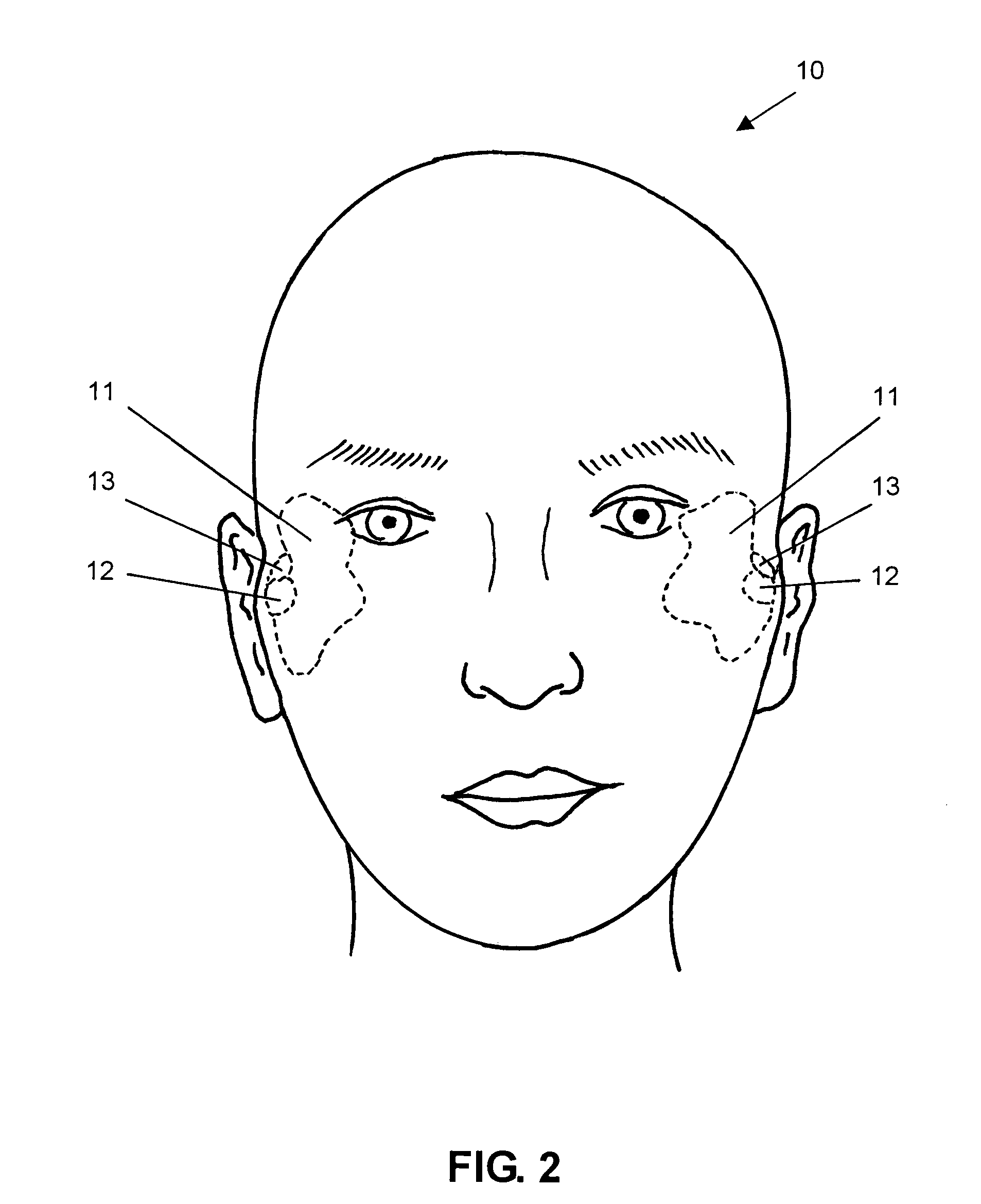
[0025]As shown in FIGS. 1 and 2, there are two zygomatic bones 11 in each human head 10. Each zygomatic bone 11 has a process extending toward the backside of the head along the temple area and is called as the temporal process of the zygomatic bone 12. On the top of the temporal process of the zygomatic bone 12, there is a ridgeline that further extends towards backside of the head through th...


PUM


Abstract

Eyeglass structures having mounting supports in temple members are provided. This design eliminates conventional nose pads and is free from any physical contact with nose. It provides a comfortable and stylish eyeglass structure to the wearer.

Description

STATEMENT REGARDING FEDERALLY SPONSORED RESEARCH OR DEVELOPMENT[0001]Not ApplicableREFERENCE TO SEQUENCE LISTING, A TABLE, OR A COMPUTER PROGRAM LISTING COMPACT DISK APPENDIX[0002]Not ApplicableBACKGROUND OF THE INVENTION[0003]The present invention relates to eyeglass structures, and more particularly to eyeglass structures having a pair of temple members whereto mounting supports are attached to secure the eyeglass structure on the ridges of the temporal process of the zygomatic bone of the wearer.[0004]Heretofore, most eyeglass structures have rested and been supported on the nose and the temple members of the eyeglass structures have rested on the ears and engaged both sides of the head behind the ears. Such eyeglass structures have the major portion of the weight thereof concentrated on the nose of the person wearing same and, therefore, tend to bear on and slide down the nose. Constant wearing of these conventional eyeglass structures often results in unsightly creases in the s...

Claims


Application Information

Patent Timeline
Patent Type & Authority Patents(United States)
IPC IPC(8): G02C5/14
CPCG02C11/00G02C3/003
Inventor KIM, BYUNG SUK
Owner KIM BYUNG SUK
Learn More