
SIM card connector with card ejection mechanism

a technology of ejection mechanism and sim card, which is applied in the direction of coupling device connection, engagement/disengagement of coupling parts, instruments, etc., and can solve the problems of mobile phone communication being interrupted, the ejection mechanism of the card is very likely to move once it is vibrated

Inactive Publication Date: 2006-03-14
CHENG UEI PRECISION IND CO LTD
View PDF6 Cites 38 Cited by
  • Summary
  • Abstract
  • Description
  • Claims
  • Application Information

AI Technical Summary

Benefits of technology

[0010]a card ejection mechanism comprising a cover slidably mounted on the housing base to form a receiving cavity for receiving a SIM card, the terminals extending into the receiving cavity for electrically connecting the SIM card, the cover having a pushing tab at a front end thereof and an operating tab at a rear end thereof, the operating tab extending upwardly for being accessible, the pushing tab extending downwardly into the receiving cavity so as to push the SIM card out from the receiving cavity when the operating tab is pulled, the cover further having a pair of side panels extending downwardly from opposite sides thereof to enclose the pair of sidewalls, at least one side panel defining a sliding slot, the locating block being received in the sliding slot to guide the sliding of the cover and prevent the cover from further sliding when the locating block engages with the ends of the sliding slot, and at least one side panel providing a hook which engages with the front notch when the SIM card is fully inserted in the receiving cavity or engages with the rear notch when the SIM card is pushed out from the receiving cavity.
[0011]As the above mentioned, when a SIM card is inserted into the SIM card connector and being in use, the cover cannot move forward relative to the housing base for the locating block engaging with the rear end of the sliding slot, and the cover cannot move backward relative to the housing base for the hook engaging with the front notch. Accordingly, the cover is secured to the housing base, and the SIM card can be reliably retained in the SIM card connector. Furthermore, when the SIM card is pushed out from the SIM card connector, the cover is also positioned because the locating block engages with the front end of the sliding slot to prevent the cover from moving backward, and the hook engages with the rear notch to prevent the cover from moving forward.
[0017]As the above mentioned, when a SIM card is inserted into the SIM card connector and being in use, the cover cannot move forward relative to the housing base because of being retained by the stopping bar, and the cover cannot move backward relative to the housing base for the hook engaging with the front notch. Accordingly, the cover is secured to the housing base, and the SIM card can be reliably retained in the SIM card connector. Furthermore, when the SIM card is pushed out from the SIM card connector, the cover is also positioned because the stopping block retains the cover to prevent the cover from moving backward, and the hook engages with the rear notch to prevent the cover from moving forward.

Problems solved by technology

When the SIM card is inserted into the SIM card connector and being in use, however, there is no positioning or locking mechanism between the card ejection mechanism and the housing base of the conventional SIM card connector, so the card ejection mechanism is very likely to move once it is vibrated.
The movement of the card ejection mechanism will make the SIM card disengage with the SIM card connector, which will cause the communication of the mobile phone to be interrupted.

Method used


Image

  • SIM card connector with card ejection mechanism
  • SIM card connector with card ejection mechanism
  • SIM card connector with card ejection mechanism

Examples


Embodiment Construction

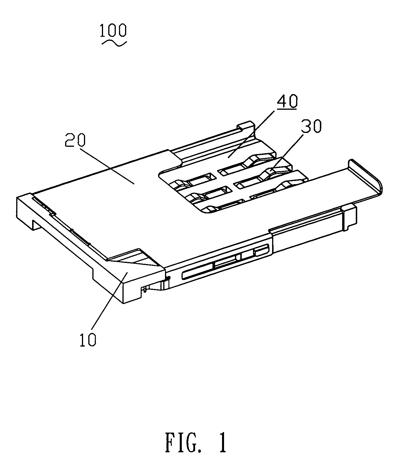
[0028]FIG. 1 shows a SIM card connector 100 with card ejection mechanism according to the present invention. The SIM card connector 100 has a housing base 10, a plurality of terminals 30 mounted in the housing base 10, and a cover 20 slidably mounted on the housing base 10 to define a receiving cavity 40 therebetween for receiving a SIM (Subscriber Identification Module) card 200 as can be seen in FIGS. 6 and 7. The cover 20 is also designed to function as a card ejection mechanism as will be described in greater detail hereinafter.

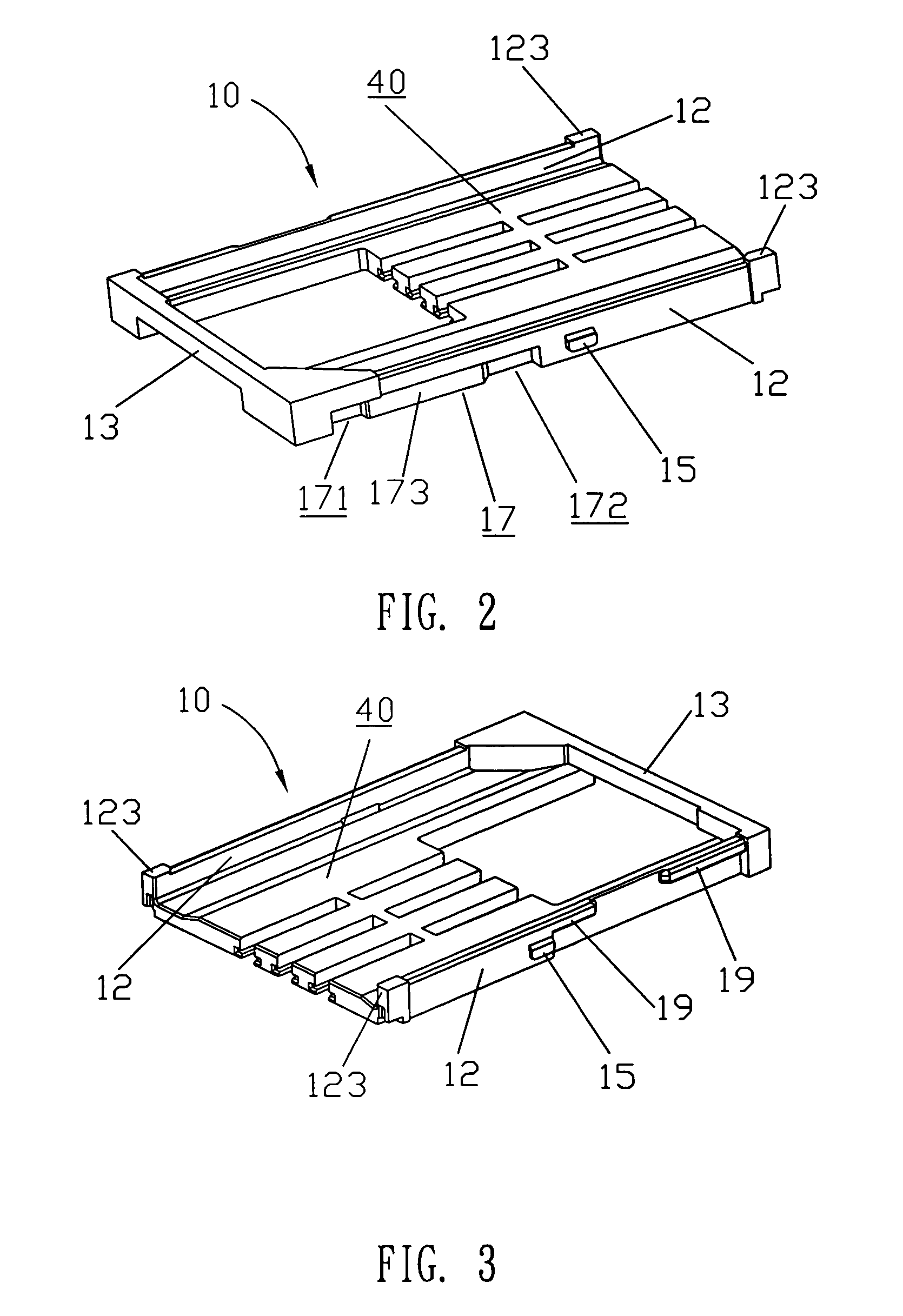
[0029]Referring to FIGS. 2 and 3, the housing base 10 has a pair of sidewalls 12 extending upwardly from two opposite sides thereof. The sidewalls 12 each have a locating block 15 projecting sideward from about middle portions thereof. One of the sidewalls 12 defines a recess 17 in the front end thereof. Two opposite ends of the recess 17 are further recessed so as to form a front notch 171, a rear notch 172, and a protruding block 173 located between the...


PUM


Abstract

A SIM card connector includes a housing base and a card ejection mechanism. The housing base has a pair of sidewalls, a front notch and a rear notch recessed in the sidewall. The card ejection mechanism includes a cover slidably mounted on the housing base to form a receiving cavity for receiving a SIM card. The cover has a pair of side panels to enclose the sidewalls. According to an aspect of the invention, the side panel defines a sliding slot. The sidewall forms a locating block received in the sliding slot to guide the sliding of the cover and prevent the cover from further sliding when the locating block engages with the ends of the sliding slot. According to another aspect of the invention, the front and rear ends of the housing base respectively form a stopping bar and a stopping block to prevent the cover from further sliding. The side panel further provides a hook which engages with the front notch when the SIM card is fully inserted in the receiving cavity to prevent the cover from moving backward or engages with the rear notch when the SIM card is pushed out from the receiving cavity to prevent the cover from moving forward.

Description

BACKGROUND OF THE INVENTION[0001]1. Field of the Invention[0002]The present invention relates to a SIM card connector with card ejection mechanism, and more particularly, to a SIM card connector capable of locating the card ejection mechanism at predetermined positions and accommodating a SIM card reliably.[0003]2. The Related Art[0004]SIM (Subscriber Identification Module) card connectors are widely applied in mobile phones to accommodate a SIM card that has the memory space to store the related information as backup data, such as the personal phone book, the phone number of the mobile phone, and the communication parameters, which can be used by the user when the communication is taken.[0005]Conventional SIM card connector with card ejection mechanism includes a housing base with an opening and a card ejection mechanism for pushing the SIM card out from the connector. The card ejection mechanism includes a main body slidably mounted in the opening of the housing base. A member of ...

Claims


Application Information

Patent Timeline
IPC IPC(8): H01R13/62
CPCG06K13/0806G06K13/08
Inventor WU, YIN-LUNG
Owner CHENG UEI PRECISION IND CO LTD
Learn More