Cooling airflow distribution device

a distribution device and airflow technology, applied in domestic cooling devices, electric apparatus casings/cabinets/drawers, instruments, etc., can solve the problems of reduced life and reliability of servers, increased total heat toad in such cabinets, and uncontrolled working temperatures

Inactive Publication Date: 2006-03-14
SANMINA-SCI CORPORATION
View PDF36 Cites 136 Cited by
  • Summary
  • Abstract
  • Description
  • Claims
  • Application Information

AI Technical Summary

Benefits of technology

[0009]According to one aspect of the invention, the distribution device is adapted such that the predetermined flow rate distribution is substantially the same (such that each vertically arrayed electronic device receives an equal portion of cooling airflow).

Problems solved by technology

This in turn has greatly increased the total heat toad in such cabinets, reaching as high as ten (10) kilowatts, with attendant problems of maintaining acceptable working temperatures inside the cabinet.
Without acceptable working temperatures, the life and reliability of the servers are reduced.
Since these servers commonly handle large amounts of sensitive and valuable data, uncontrolled working temperatures are not acceptable, and steps to maintain the servers at a relatively cool and steady temperature are required.
There are, however, several disadvantages to this method.
To begin with, energy is wasted since the whole room and the contents of the room must be cooled.
In addition, because the cabinets are mounted in rows, the heated air which exits one row of cabinets adversely affects the temperature of adjacent rows of cabinets.
Furthermore, upgrading existing installations by the addition of cabinets filled with high density servers may not be possible since the cooling capacity of existing room air-conditioning units may be exceeded.
Also, with the shortages of available electrical power, the demand of new room air-conditioner systems may not be met by the public utility.
Such units, however, occupy valuable floor area that could be more profitably occupied by a server cabinet.

Method used


Image

  • Cooling airflow distribution device
  • Cooling airflow distribution device
  • Cooling airflow distribution device

Examples


Embodiment Construction

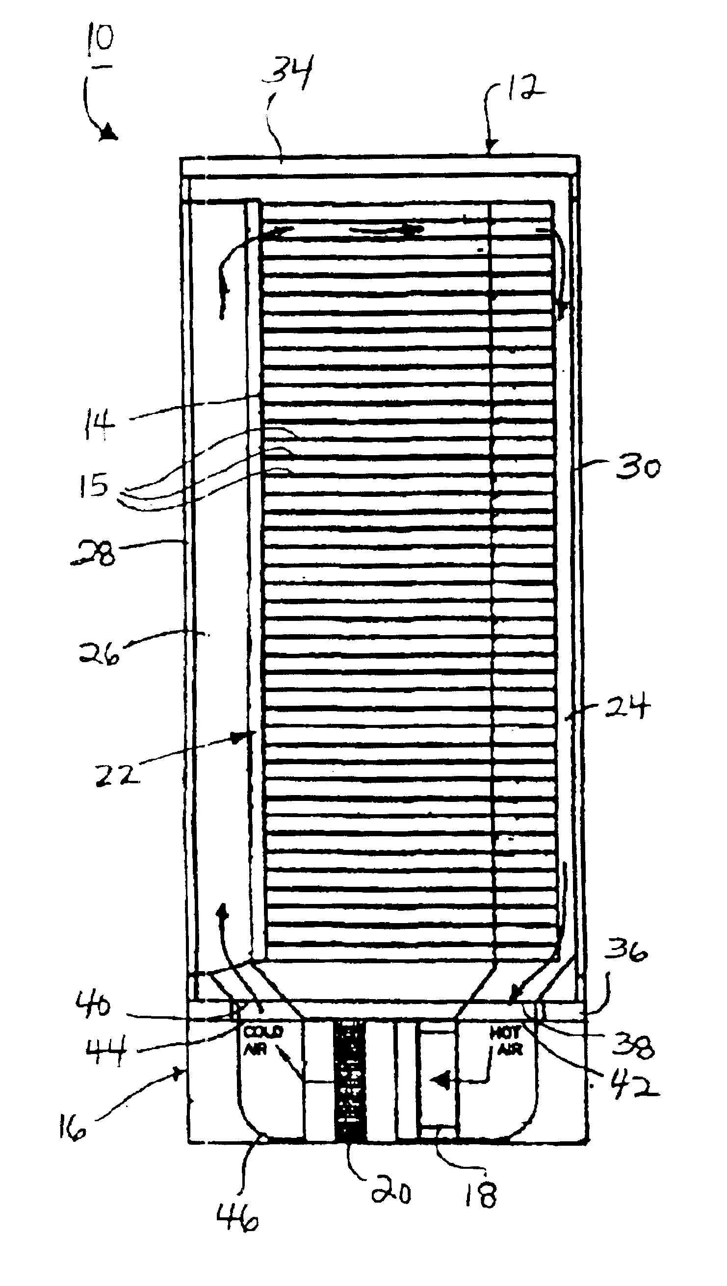
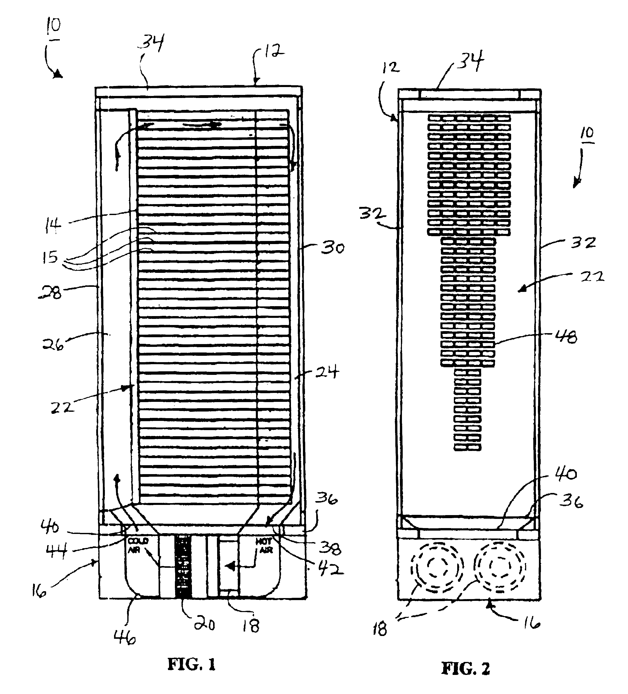
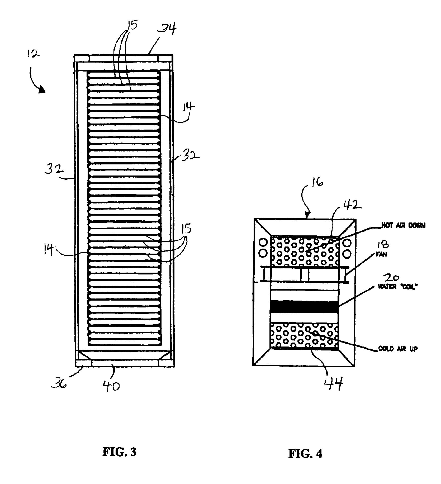
[0034]Referring to FIGS. 1 through 4, the present disclosure provides a new and improved system 10 for removing heat from a plurality of electronic assemblies, such as data servers. The system 10 includes at least one cabinet 12 containing means 14 for supporting electronic assemblies such as data servers, at least one plinth 16 containing means 18 for creating an airflow through the cabinet 12 and means 20 for removing heat from the airflow, and at least one air flow distribution device 22 for establishing a predetermined flow rate distribution through the cabinet 12.

[0035]Typical applications for the presently disclosed system 10 are found in “data centers” that contain hundreds of cabinets containing “servers” or other electronic data equipment. The equipment may, for example, be used for telecommunication purposes or for high speed internet or streaming data services. In the embodiment shown, the means for supporting the electronic assemblies comprise brackets 14 arranged to sup...


PUM


Abstract

A system for removing heat from a plurality of electronic assemblies including a cabinet having brackets for supporting electronic assemblies in a vertical array between a first vertical airflow path and a second vertical air flow path of the cabinet, and a plinth underlying the cabinet and having an input port receiving air from the first vertical airflow path of the cabinet, an output port transmitting air to the second vertical air flow path, a heat exchanger positioned in an air flow path extending between the input and the output ports, and a fan assembly for driving air through the heat exchanger and towards the input port. The system further includes at least one air flow distribution device establishing a predetermined flow rate distribution through electronic assemblies supports by the brackets.

Description

CROSS-REFERENCE TO RELATED APPLICATION[0001]The present application claims priority to International Application for Patent Serial No. PCT / IB02 / 03067, filed May 15, 2002, the disclosure of which is incorporated herein by reference in its entirety. International Application for Patent Serial No. PCT / IB02 / 03067, in turn, claims priority and is a continuation in part of U.S. patent application Ser. No. 09 / 927,659, filed Aug. 10, 2001, now U.S. Pat. No. 6,506,111, and provisional U.S. patent application Ser. No. 60 / 291,447, filed May 16, 2001.FIELD OF THE INVENTION[0002]This invention relates to a method and system for removing heat from electronic data servers or similar equipment and, more particularly, to a system having a closed cabinet for supporting electronic assemblies, a plinth for providing a cooling airflow to the interior of the cabinet, and distribution devices for distributing the cooling airflow within the cabinet.BACKGROUND OF THE INVENTION[0003]The advent of high-densit...

Claims


Application Information

Patent Timeline
Patent Type & Authority Patents(United States)
IPC IPC(8): H05K5/00F25D9/00G06F1/20H05K7/20
CPCH05K7/20754
Inventor SHARP, ANTHONY C.HUDZ, ANDREWJEFFERY, PETER
Owner SANMINA-SCI CORPORATION
Why Eureka
Try Eureka