Transmit/receive phased array coil system

a phased array coil and transmission coil technology, applied in the field of coils, can solve problems such as the problem of artifacts, image provided using the prior art receiving coils could have artifacts, and the problem of improving the problem of this type of artifact, so as to improve the signal to noise performance

Inactive Publication Date: 2006-03-14
BAYER HEALTHCARE LLC
View PDF31 Cites 61 Cited by
  • Summary
  • Abstract
  • Description
  • Claims
  • Application Information

AI Technical Summary

Problems solved by technology

However, the various receiving coils of the prior art described had a number of artifact problems.
For example, an image provided using the prior art receiving coils could have artifacts due to aliasing caused when the phase of a signal from a part of the anatomy within the field of the coil duplicates that of a location elsewhere.
The problems associated with this type of artifact are worsened by the use of higher speed gradients that are shorter in physical size and lower field uniformity.

Method used


Image

  • Transmit/receive phased array coil system
  • Transmit/receive phased array coil system
  • Transmit/receive phased array coil system

Examples


Embodiment Construction

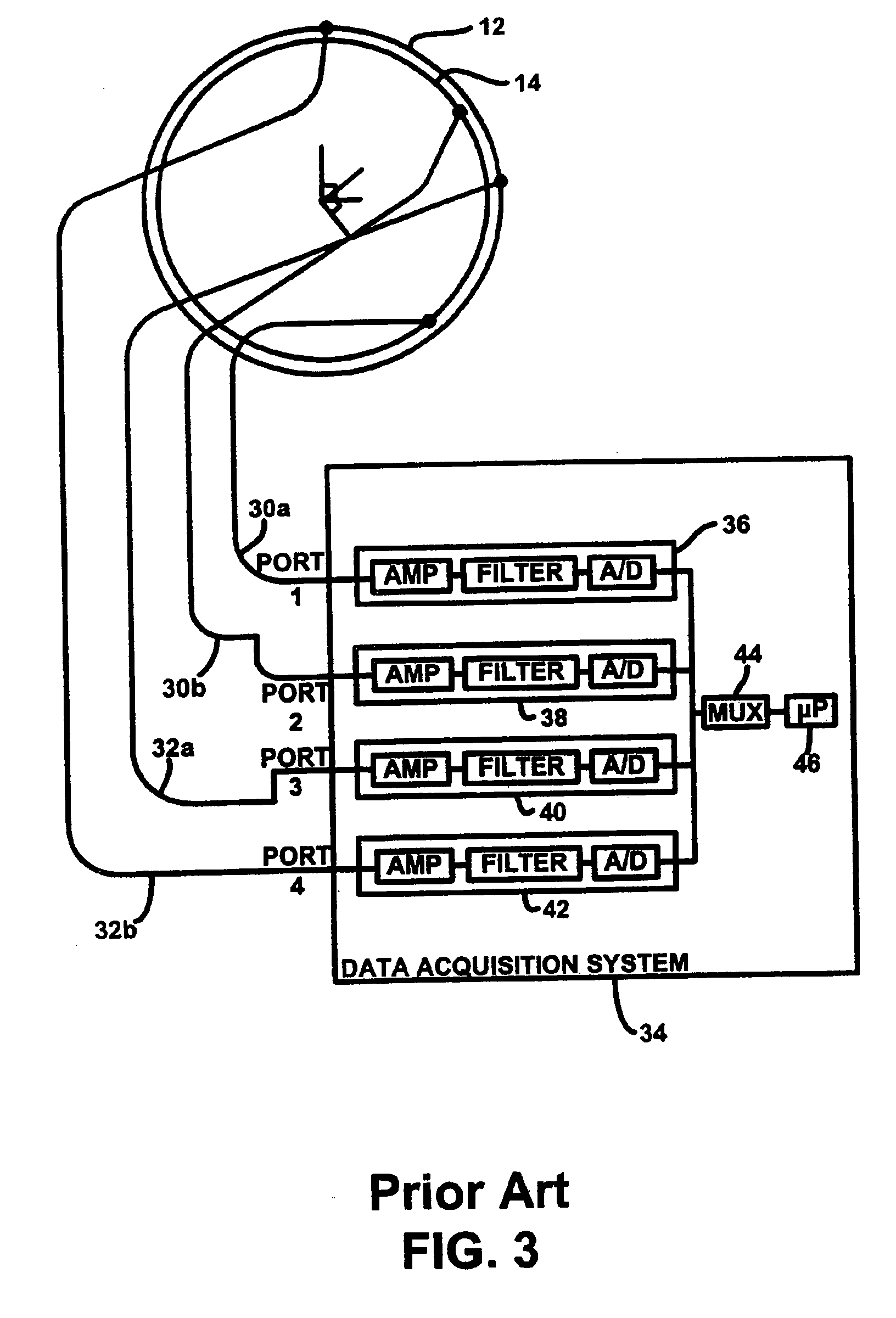
[0023]Referring now to FIGS. 1 and 2, there is shown a prior art multiple quadrature receiving coil system 10. This prior art multiple quadrature receiving coil system 10 was formed of quadrature receiving coils 12 and 14, which were designed for a variety of anatomical regions of the body, such as the knee, leg, arm or head. Quadrature receiving coils 12, 14 of quadrature receiving coil system 10 are thus volume coils. Coils 12, 14 are disposed around a hollow cylindrical drum support member 16. Support rods 18 extending the length of cylindrical drum 16 can be provided to stabilize the cylindrical drum support member 16.

[0024]Quadrature receiving coils 12, 14 are of a type referred to as birdcage coils, as well known in the art. They are formed of circular conductive loops 20, 22 connected to each other and spaced apart from each other by conductive connection members 24. There may be eight electrically conductive connection members 24 or rods 24 joining circular conductive loops ...


PUM


Abstract

A phased array coil system is presented for use with a magnetic resonance system. The phased array coil system includes a first coil, a second coil, and an interface subsystem. The first coil defines a first region and the second coil defines a second region, with the first coil partially overlapping the second coil to define an overlap region formed by the intersection of the first and second region. Operably connected with the first and second coils, the interface subsystem includes (i) a power splitter for splitting radio frequency (RF) power for delivery to the first and second coils and (ii) a phase compensator for adjusting the phase relationship of the RF power delivered to the first and second coils so that a magnetic field produced thereby in the overlap region is approximately equal to that produced near the center of each of the first and second regions.

Description

CROSS-REFERENCE TO RELATED APPLICATIONS[0001]This application for patent is a continuation of U.S. application Ser. No. 10 / 151,491, filed May 20, 2002 now U.S. Pat. No. 6,714,013, which is a continuation of U.S. application Ser. No. 09 / 776,132, filed Feb. 2, 2001, now U.S. Pat. No. 6,396,273, which is a continuation of U.S. application Ser. No. 09 / 512,093, filed Feb. 24, 2000, now abandoned, which is a divisional of U.S. application Ser. No. 08 / 979,842, filed Nov. 26, 1997, now U.S. Pat. No. 6,040,697, the contents of which are incorporated herein by reference.BACKGROUND OF THE INVENTION[0002]The present invention relates to the field of magnetic resonance imaging (MRI) systems and, more particularly, to coils for use in such systems.[0003]It is well known in the field of MRI systems to provide radio frequency signals in the form of circularly polarized or rotating magnetic fields having an axis of rotation aligned with a main magnetic field. It is also well known to use receiving c...

Claims


Application Information

Patent Timeline
Patent Type & Authority Patents(United States)
IPC IPC(8): G01V3/00G01R33/3415
CPCG01R33/3415
Inventor MISIC, GEORGE J.
Owner BAYER HEALTHCARE LLC
Why Eureka
Try Eureka