Image forming apparatus

a technology of image forming apparatus and components, which is applied in the direction of electrographic process apparatus, instruments, optics, etc., can solve the problems of increasing the number of components in the main body of the image forming apparatus and complicated configuration, and achieve the effect of reducing the number of components

Active Publication Date: 2006-03-14
CANON KK
View PDF6 Cites 18 Cited by
  • Summary
  • Abstract
  • Description
  • Claims
  • Application Information

AI Technical Summary

Benefits of technology

[0032]It is an object of the present invention to reduce the number of components in an image forming apparatus.

Problems solved by technology

However, in order to provide such an another ventilation channel in the main body of the image forming apparatus when mounting the fixing unit, it is necessary to newly mount a plurality of components in the image forming apparatus, resulting in an increase in the number of components in the main body of the image forming apparatus, and a complicated configuration.

Method used


Image

  • Image forming apparatus
  • Image forming apparatus
  • Image forming apparatus

Examples


first embodiment

(First Embodiment)

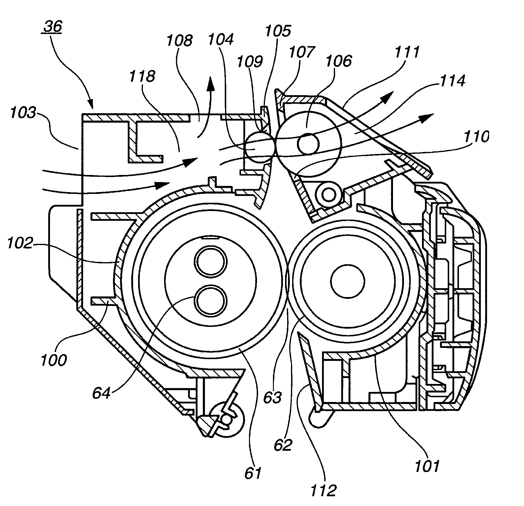
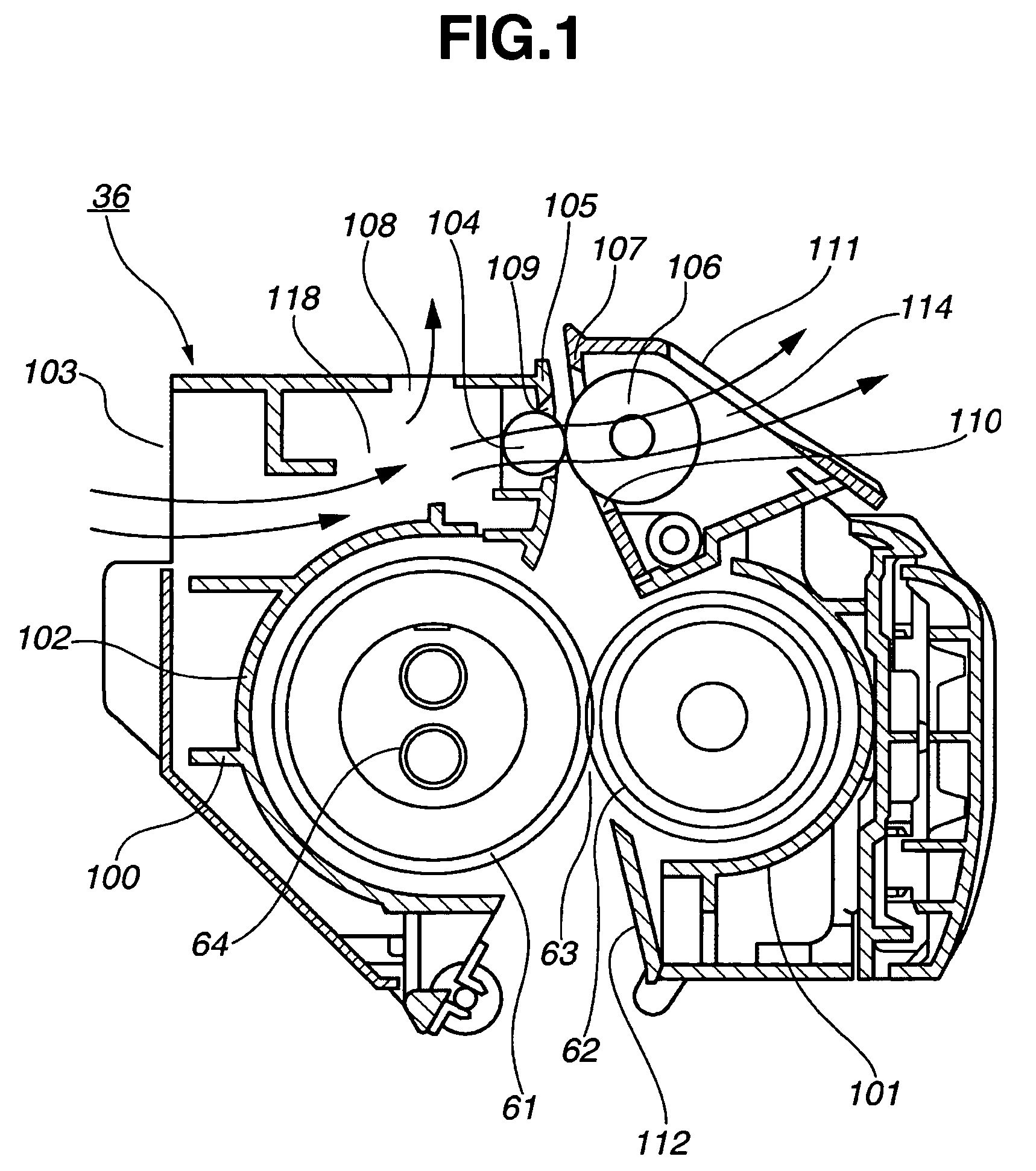
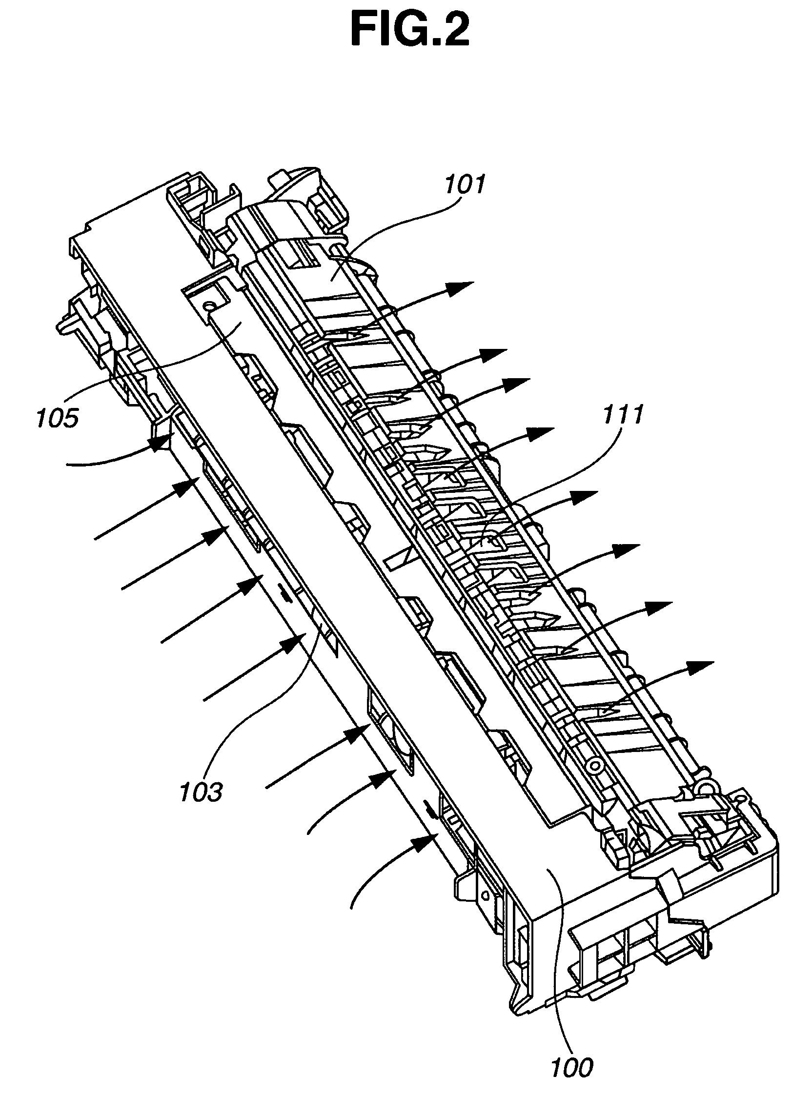
[0042]A first embodiment of the present invention will now be described with reference to FIGS. 1, 2 and 4.

[0043]FIG. 4 illustrates a color copier, serving as an image forming apparatus mounting a heating fixing unit, serving as a fixing device, according to the first embodiment.

[0044]The configuration of the color copier of the first embodiment is the same as the above-described one. As shown in FIG. 4, the color copier includes an original-reader unit 50, an original-reading device 52, and a printer unit 20 to form an image on a recording material. The printer unit 20 has the same configuration as the above-described one, except for a fixing unit 36 to which the present invention is applied. Accordingly, the fixing unit 36 of the first embodiment will now be described.

[0045]As shown in FIG. 1, the fixing unit 36 includes a pair of a fixing roller 61, serving as a heating member provided by forming a rubber layer on the surface of a core, and a pressing roller 62,...

second embodiment

(Second Embodiment)

[0068]A second embodiment of the present invention will now be described with reference to FIGS. 3 and 4. As in the first embodiment, a fixing unit 36 of the second embodiment is mounted in the color copier shown in FIG. 4, or the like. The fixing unit 36 of the second embodiment will now be described.

[0069]As shown in FIG. 3, the fixing unit 36 includes a pair of a film 151, serving as a fixing rotating member, having a ceramic heater 150, serving as a heater, therein, and a pressing roller 152, serving as a pressing member. By pressing the pressing roller 152 against the ceramic heater 150 via the film 151, a nip portion 153 is formed. The film 151 having the ceramic heater 150 and the pressing roller 152 constitute heating means.

[0070]When the fixing unit 36 is operating, a sheet conveyed from below is conveyed by being grasped at the nip portion 153 between the film 151 heated by the ceramic heater 150, and the pressing roller 152, and a toner image is fixed b...


PUM


Abstract

An image forming apparatus includes an unfixed-image forming unit for forming an unfixed image, and a fixing unit. The fixing unit includes a heating member for heating the unfixed image, and a heat insulating member having an interval with the heating member and disposed so as to cover the heating member along the heating member in a direction perpendicular to a conveying direction of a recording material, for insulating heat from the heating member. The fixing unit is detachably mountable in the image forming apparatus, and fixes the unfixed image on the recording material formed by the unfixed-image forming unit. The apparatus also includes an exhaust fan disposed near the fixing unit, for exhausting air from within the image forming apparatus. The fixing unit has a ventilation channel passing through the fixing unit outside of the heat insulating material.

Description

BACKGROUND OF THE INVENTION[0001]1. Field of the Invention[0002]The present invention relates to an image forming apparatus.[0003]2. Description of the Related Art[0004]An electrophotographic image forming apparatus usually includes a fixing device in which a toner, made of resin, a magnetic material, a coloring agent and the like, that is electrostatically held on a transfer material is fused and fixed by applying heat and pressure while grasping and conveying the transfer material and the toner at a pressing portion (nip portion) between heating means (a roller, an endless belt, or the like) and pressing means (a roller, an endless belt, or the like).[0005]The configuration and the operation of a heating fixing unit, serving as a conventional fixing device, and the configuration and the operation of a color copier, serving as an image forming apparatus having the heating fixing unit will now be described with reference to FIGS. 4 and 5.[0006]FIG. 4 is a cross-sectional view illust...

Claims


Application Information

Patent Timeline
Patent Type & Authority Patents(United States)
IPC IPC(8): G03G15/00G03G15/20G03G21/20
CPCG03G21/206G03G15/2003
Inventor SHIRAKATA, JIRO
Owner CANON KK
Why Eureka
Try Eureka