Rapid graphical analysis of waveforms using a pointing device

a waveform and pointing device technology, applied in the field of displays, can solve the problems of several steps for parametric parameters and is not immediately intuitiv

Inactive Publication Date: 2006-03-14
KEYSIGHT TECH
View PDF11 Cites 12 Cited by
  • Summary
  • Abstract
  • Description
  • Claims
  • Application Information

AI Technical Summary

Problems solved by technology

Generally, varying any of these parameters requires several steps and is not immediately intuitive.

Method used


Image

  • Rapid graphical analysis of waveforms using a pointing device
  • Rapid graphical analysis of waveforms using a pointing device
  • Rapid graphical analysis of waveforms using a pointing device

Examples


Embodiment Construction

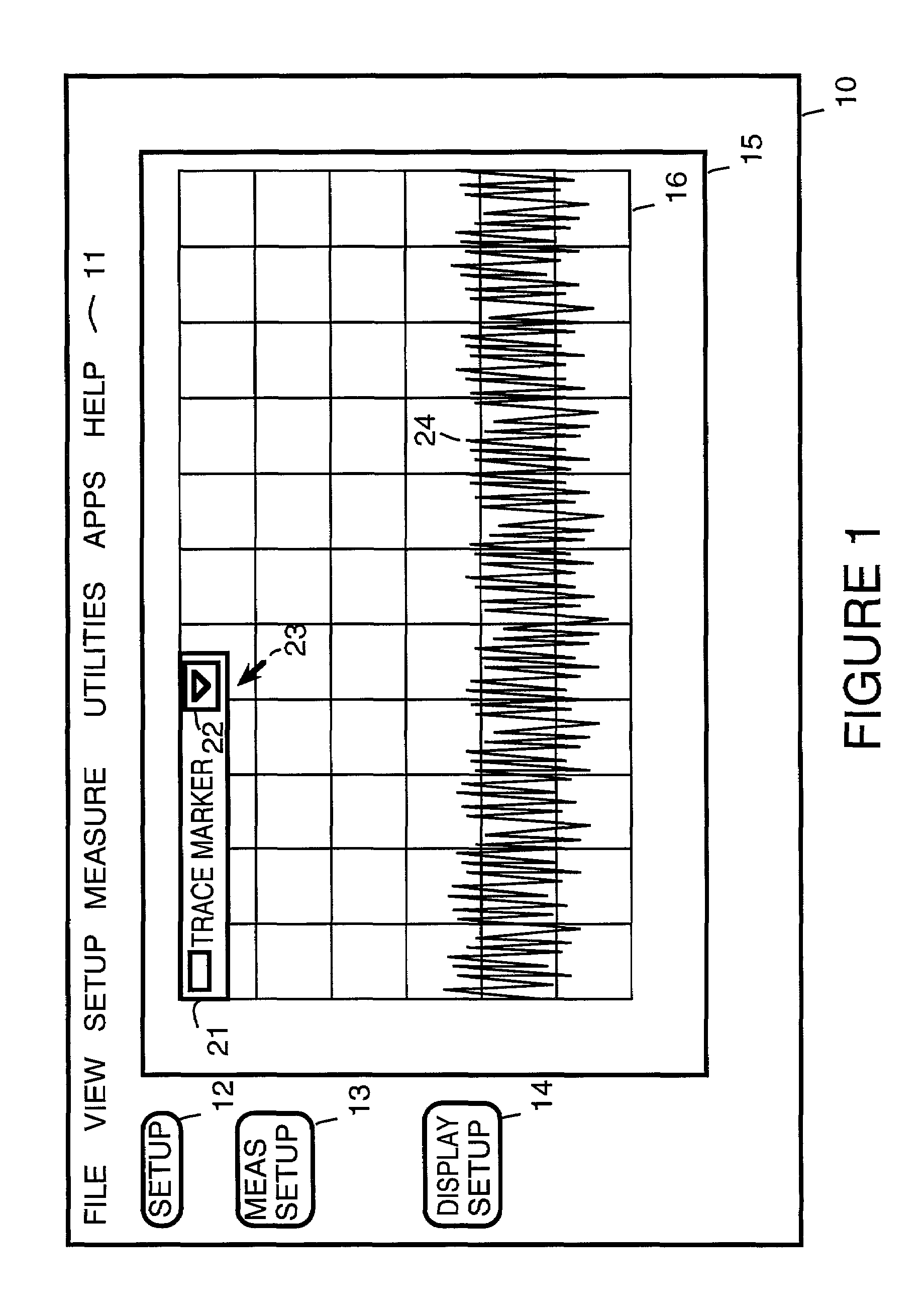
[0012]FIG. 1 shows a simplified display 10 from a multi-wavelength meter that shows the selected parameter “trace marker” on a pull down menu 21. The complete pull down menu displayed by using a pointing device, represented by a cursor 23, to select button 22. The pointing device is, for example, a mouse, trackball, touchpad, and so on. Alternatively, the pointing device can be implemented using a touchscreen implementation of display 10, cursor keys, or by any other means that allows selecting elements on a display.

[0013]Display 10 includes a grid 16 within a window 15. On grid 16 is displayed a measured signal 24. Also shown within display 10 are a menu 11, a button 12, a button 13 and a button 14.

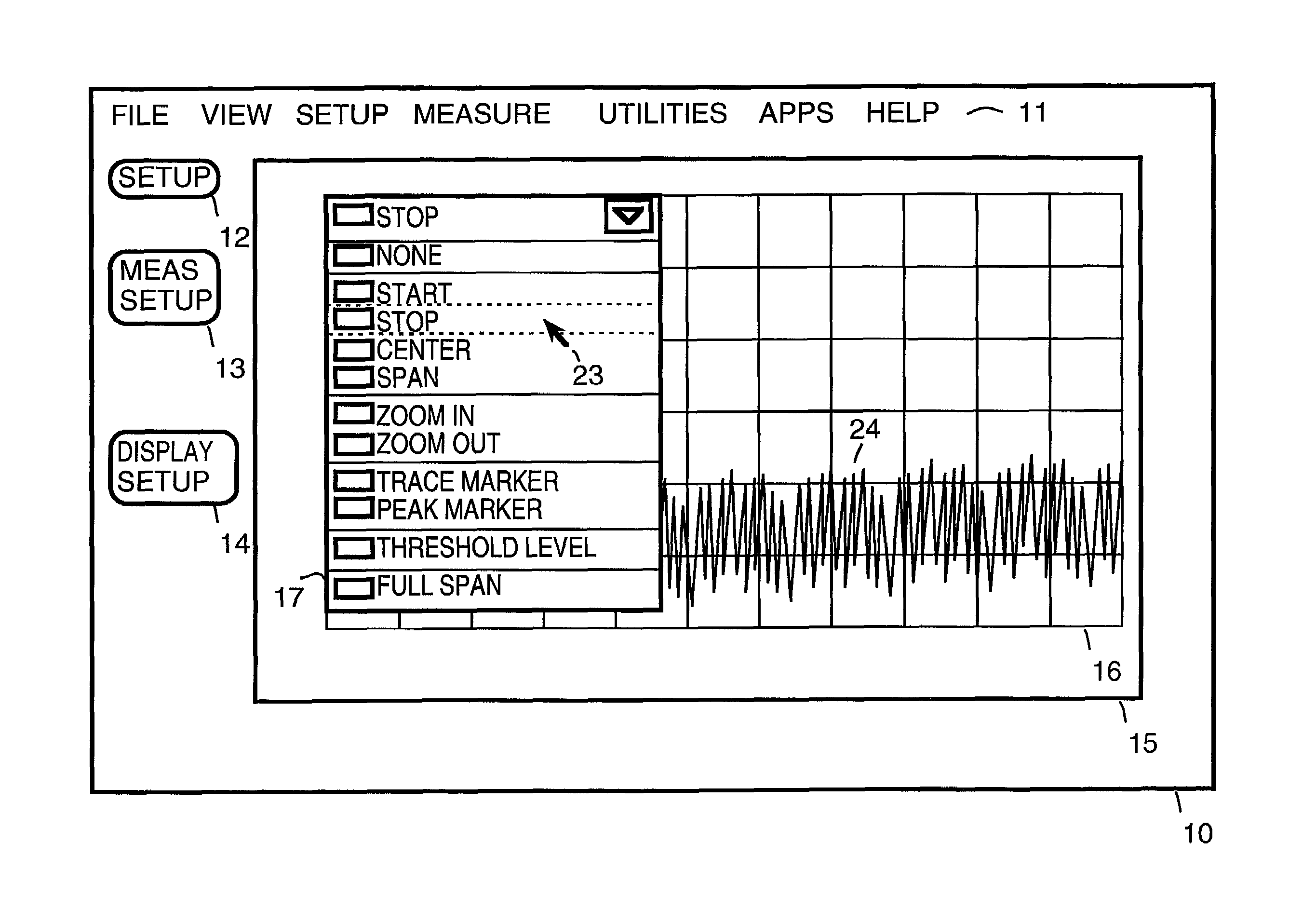
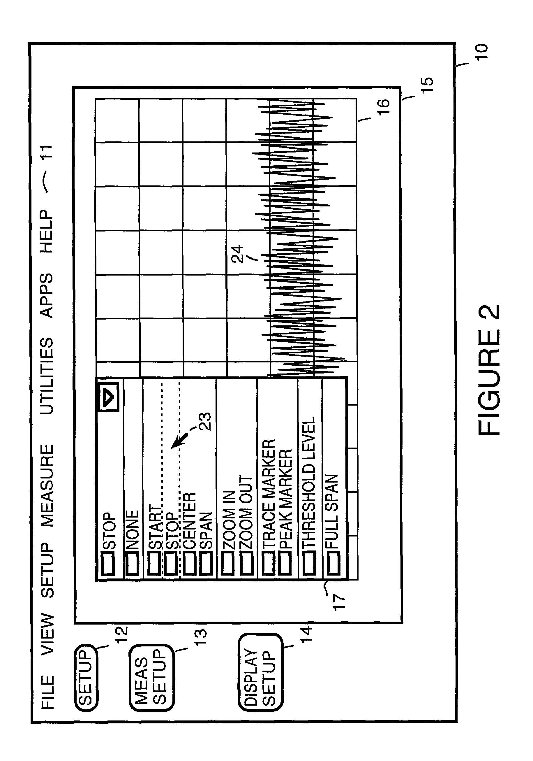
[0014]FIG. 2 shows the result when button 22 is selected by the pointing device. A full menu 17 is shown. On menu 17 are listed various parameters that may be varied using a pointing device. Shown in FIG. 17 are the following parameters: start, stop, center, span, zoom in, zoom out, trac...


PUM


Abstract

A signal waveform is displayed on a display. In response to a user using a pointing device to select a location on the display, values for a selected parameter of the displayed signal waveform are adjusted based on locations on the display selected by the user using the pointing device.

Description

BACKGROUND[0001]The present invention concerns displays used for electronic instruments and other devices and pertains particularly to rapid graphical analysis of waveforms using a pointing device.[0002]A spectrum analyzer displays the amplitude of signals on the vertical (y) axis and frequency on the horizontal (x) axis. For some existing spectrum analyzers, when observing a measured signal, the displayed frequency component can be adjusted using start, stop, center or span controls. This is typically accomplished using a knob, step keys or direct numerical input. Generally, varying any of these parameters requires several steps and is not immediately intuitive. For example, to zoom in on a specific signal typically requires alternating between the center and span controls.[0003]For further information on how center, start, stop and span controls work on existing spectrum analyzers, see for example, the User's Guide Agilent Technologies ESA Series Spectrum Analyzers, available from...

Claims


Application Information

Patent Timeline
Patent Type & Authority Patents(United States)
IPC IPC(8): G06F3/14G06F17/00G01R13/02G06F3/033G06F3/048
CPCG01R13/02G06F3/04847G06F3/04845
Inventor JAFFE, STANLEY EDWARD
Owner KEYSIGHT TECH
Why Eureka
Try Eureka