Vertical machining center

a technology of vertical machining and center, which is applied in the direction of turning machine accessories, manufacturing tools, metal working devices, etc., can solve the problem of complicated over-all structure of the devi

Inactive Publication Date: 2006-03-21
MORI SEIKI HITECH
View PDF3 Cites 21 Cited by
  • Summary
  • Abstract
  • Description
  • Claims
  • Application Information

AI Technical Summary

Benefits of technology

[0009]Accordingly, in order to overcome the above-noted defects, an object of the present invention is to provide a space-saving vertical machining center which may perform to stock, feed and machine bar workpieces even without providing a feeding device having a complicated structure for pushing the bar workpiece.
[0014]When the swing drive unit is driven, the bar workpiece is indexed under the conditions that the bar workpiece is kept in a slanted direction in addition to the horizontal direction to thereby make it possible to perform various turning and cutting operations in a predetermined desired manner.
[0017]Preferably, the stocker comprises: a stocker body provided with an index drive unit for indexing the bar workpiece at the receiving and discharging position; a swivel portion, for swiveling about a swivel axis, mounted horizontally on an upper portion of the stocker body; and a plurality of receiving sleeves fixed on a top surface of the swivel portion and arranged to be directed upwardly in parallel with the swivel axis, wherein the receiving sleeve is opened upwardly and forms a cylindrical shape or a bottomed cylindrical shape, and the bar workpiece is moved in an up-and-down direction in parallel with the swivel axis so that it is possible to insert the bar workpiece into the receiving sleeve and to remove the bar workpiece out of the receiving sleeve.
[0022]With such an arrangement, according to the present invention, it is possible to provide a space-saving vertical machining center which performs the operations such as stocking, feeding and machining the bar workpiece even without providing a feeding device having a complicated structure for pushing the bar workpieces.

Problems solved by technology

As a result, the overall structure of the device becomes complicated.

Method used


Image

  • Vertical machining center
  • Vertical machining center
  • Vertical machining center

Examples


Embodiment Construction

[0026]An embodiment of the present invention will now be described with reference to the accompanying drawings FIGS. 1 to 3J.

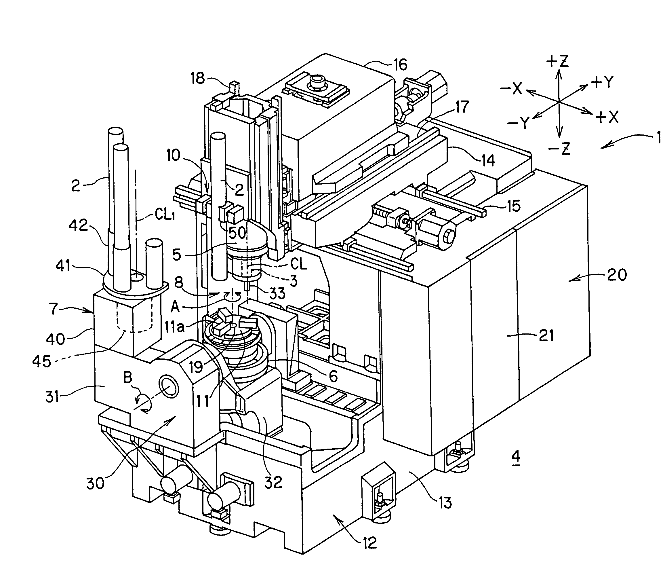
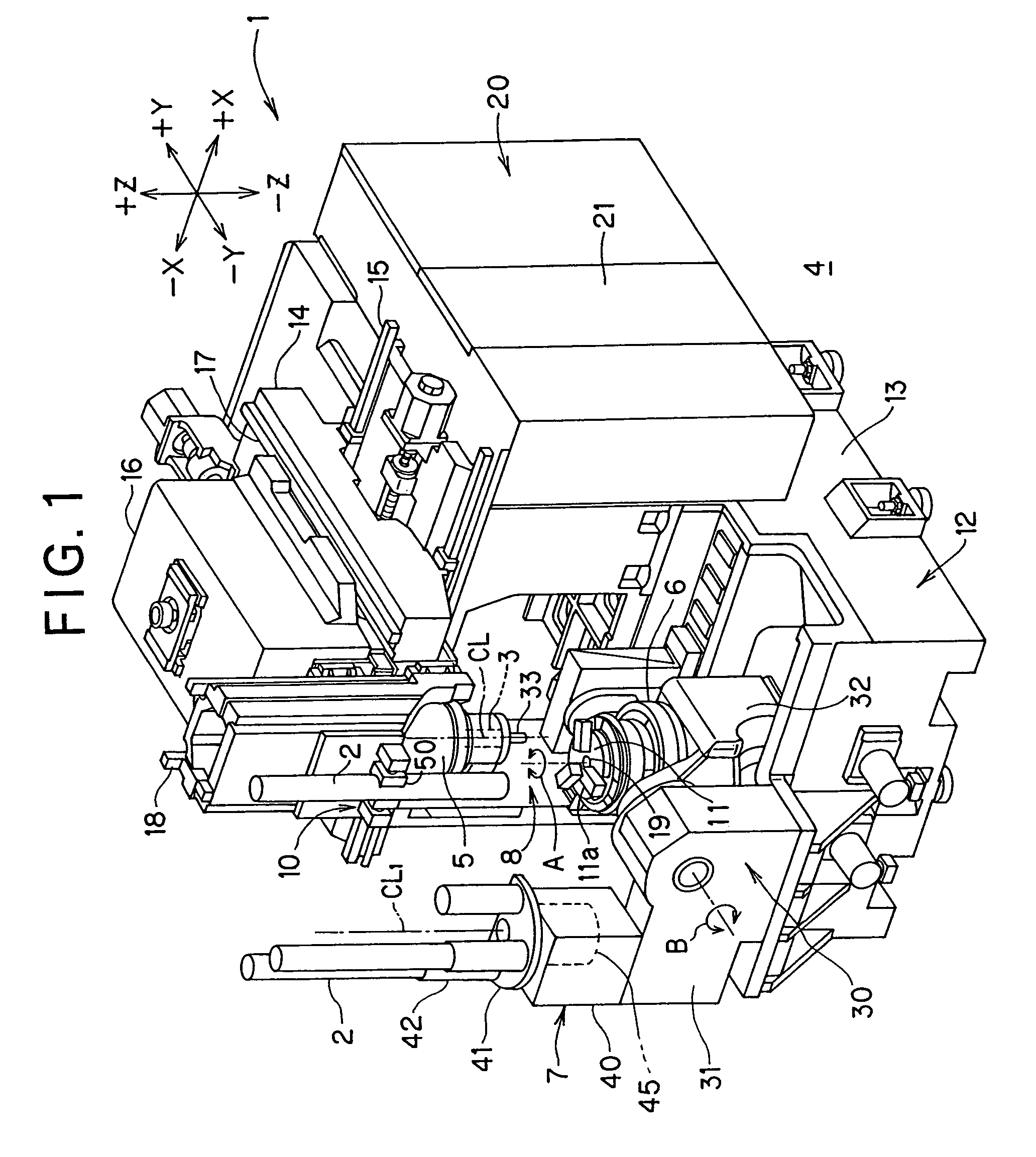
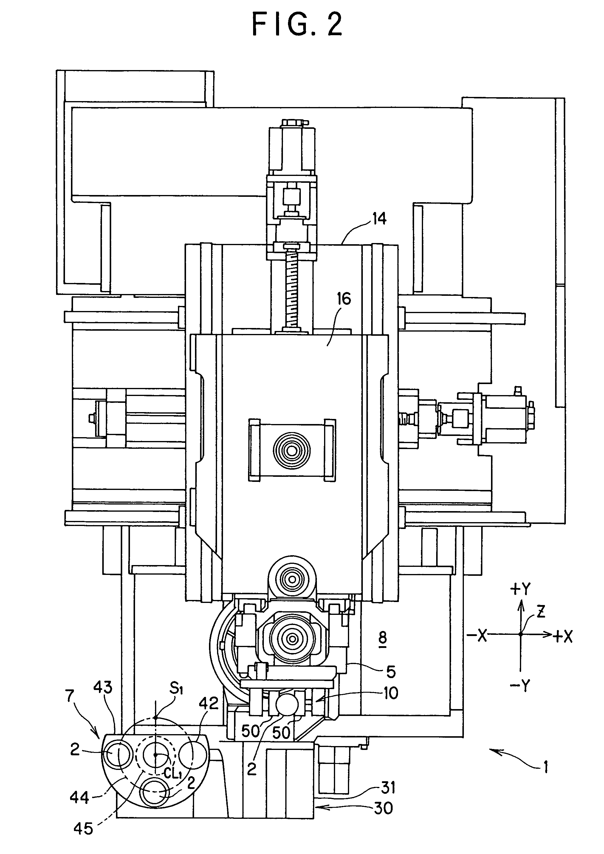
[0027]FIG. 1 and FIG. 2 are a perspective view and a plan view of a vertical machining center, respectively. FIGS. 3A to 3J are illustrations of the operations of the vertical machining center.

[0028]FIG. 1 and FIG. 2 show the vertical machining center (hereinafter referred to as MC) 1 according to this embodiment. This MC 1 is a machine tool which may perform at least turning to a bar workpiece 2 as a workpiece in a five-axis control.

[0029]The MC 1 is controlled by a controller 20 which is composed of an NC (numerical control) unit and a programmable logic controller (PLC). Incidentally, the controller 20 may be a controller in which the PLC portion is built in the NC unit.

[0030]An axis CL of a main spindle 3 of the MC 1 is directed in the vertical direction to a floor surface 4. Incidentally, the axis CL may be directed in a direction which is slanted at a pr...


PUM

PropertyMeasurementUnit
diameteraaaaaaaaaa
diameteraaaaaaaaaa
rotational speedsaaaaaaaaaa

Abstract

In a vertical machining center, a spindle head is movable in three mutually transverse axes directions relative to a workpiece and a table is arranged below. A vertical stocker is disposed in the vicinity of a machining area and stocks the bar workpiece in a vertical direction. A hand portion which grips and releases the bar workpiece is provided on the spindle head. The spindle head moves between the stocker and the table so that the hand portion transfers the bar workpiece and performs putting and removing the bar workpiece to the stocker and a chuck of the table, respectively.

Description

BACKGROUND OF THE INVENTION[0001]1. Field of the Invention[0002]The present invention relates to a vertical machining center which may machine a bar workpiece.[0003]2. Description of the Related Art[0004]An axis of a main spindle of a vertical machining center is directed in the vertical direction. A bar workpiece (i.e., a bar member or a bar work) having an axial dimension longer than a radial dimension is a kind of workpiece. A technology, in which a bar workpiece is fed by a bar feed device (a bar workpiece feeding device) to perform a turning by a turning tool and to perform a cutting by a rotating tool to the bar workpiece, is known in the vertical machining center.[0005]Also, the U.S. Pat. No. 6,131,259 discloses a technology relating to a vertical machining center provided with a bar member feeding device (bar feed device).[0006]This vertical machining center has a horizontal bar member feed device for arranging the bar workpiece in the horizontal direction. The bar member (b...

Claims


Application Information

Patent Timeline
Patent Type & Authority Patents(United States)
IPC IPC(8): B23Q7/04B23Q7/10B23P17/00
CPCB23Q7/045Y10T29/5114Y10T82/2516Y10T409/30532Y10T82/2511
Inventor IWABUCHI, NAOKIKIMURA, HAJIMEFUJIWARA, RYUICHI
Owner MORI SEIKI HITECH
Why Eureka
Try Eureka