Internal cross over valve
a cross-over valve and internal technology, applied in the field of valves, can solve the problems of expensive and bulky equipment attached to each compartment, and achieve the effect of improving the service life and reducing the cost of equipmen
- Summary
- Abstract
- Description
- Claims
- Application Information
AI Technical Summary
Benefits of technology
Problems solved by technology
Method used
Image
Examples
first embodiment
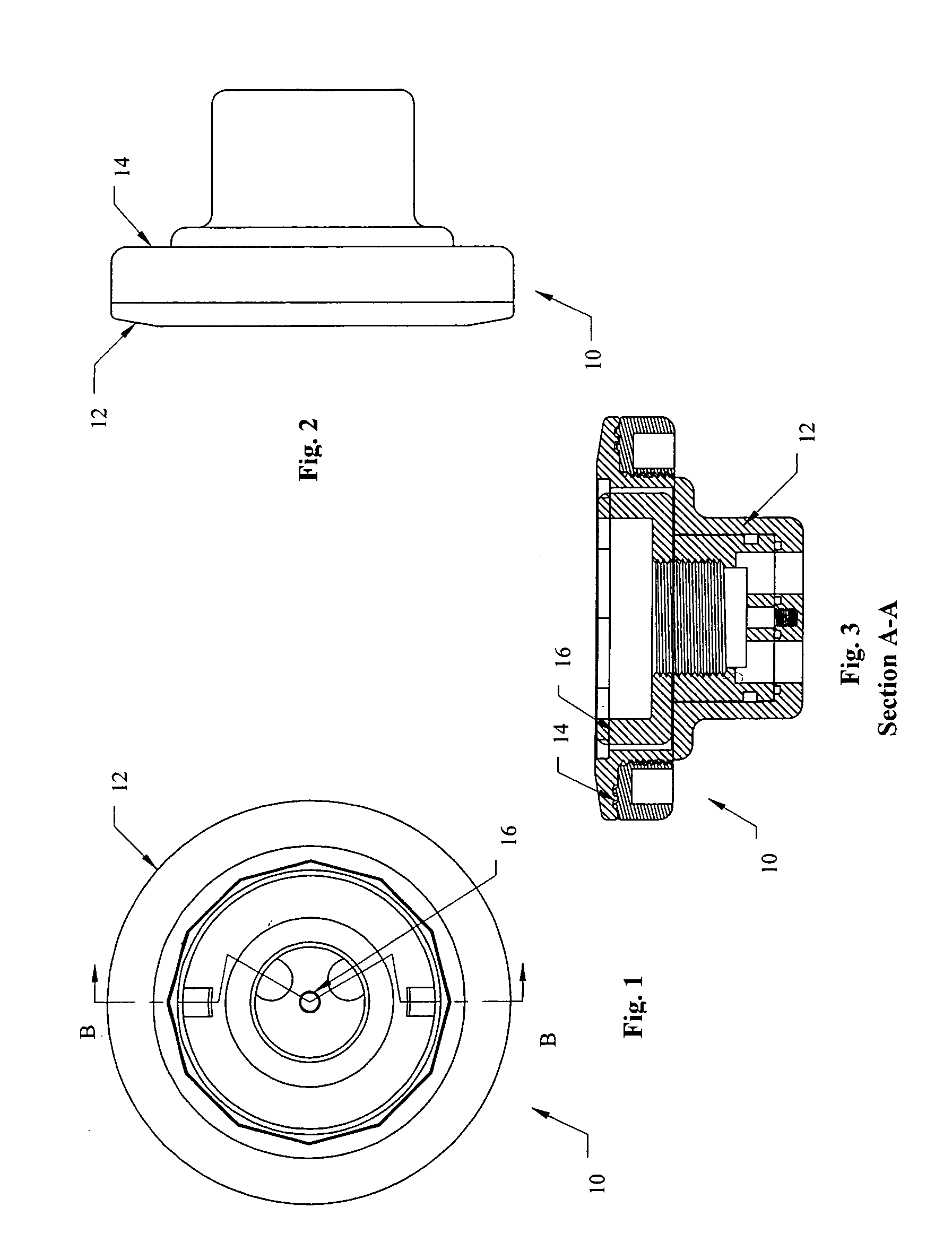
[0049]the internal cross over valve assembly is shown in FIGS. 1–15 and indicated as 10. Internal cross over valve assembly 10 includes a top flange 12, a valve retainer 14, and a valve spool 16.
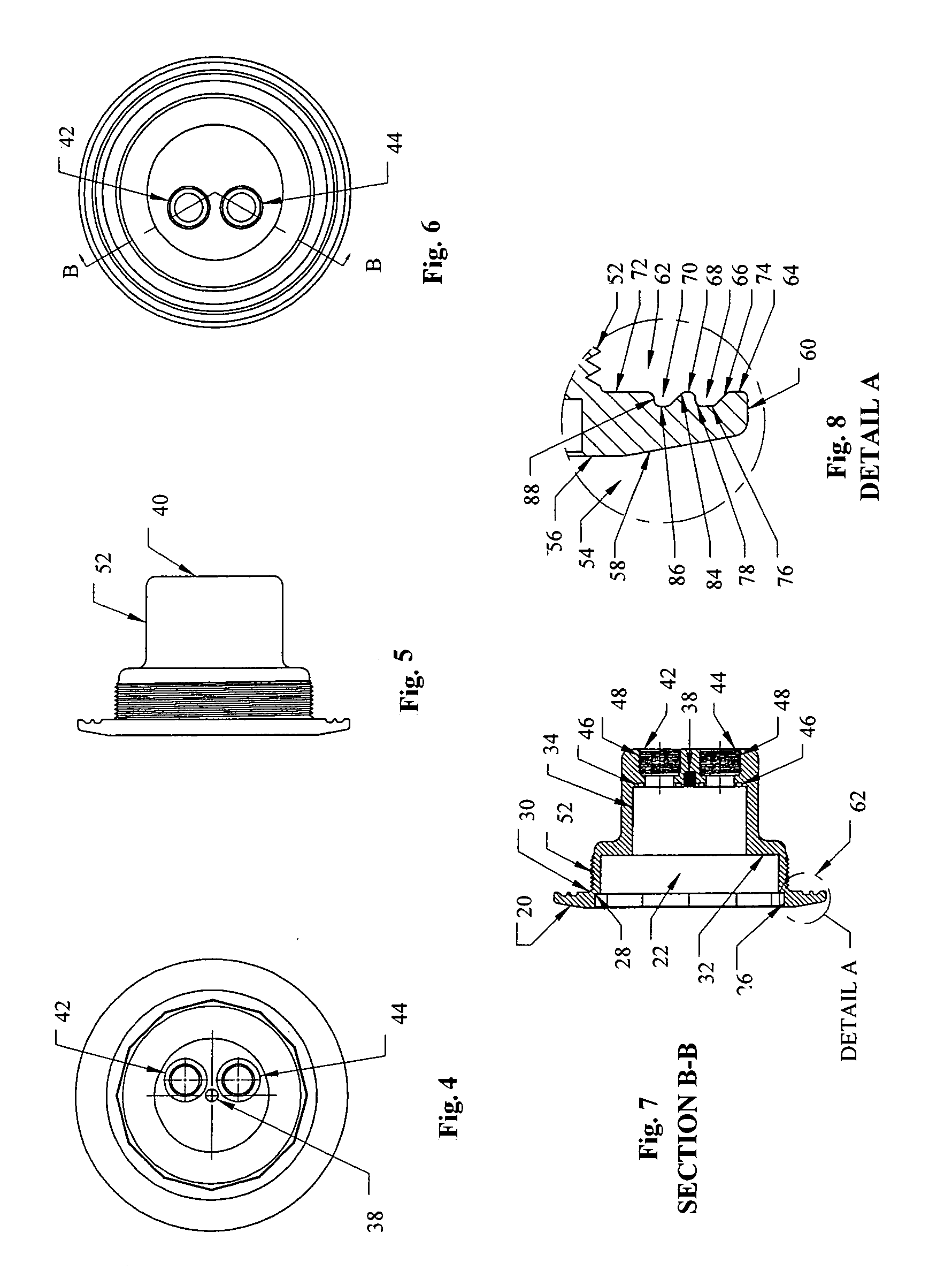
[0050]Top flange 12 is best shown in FIGS. 4–8. Top flange is of a stepped cylindrical design such that the flange 12 includes a circular flange 20 with an aperture 22 in the center thereof defining a well 24 that includes a larger diameter portion 26, a ledge 28, an intermediate diameter portion 30, a seat 32, and a smaller diameter portion 34. At the base 36 of the well is a threaded shaft 38 extending only partially into flange bottom 40 as best shown in FIG. 4, and a pair of pores 42 and 44 which are offset as is best shown in FIGS. 4 and 6. Each port 42 and 44 includes a smaller diameter section 46 adjacent the base 36 and extending to a larger diameter threaded section 48 extending through to flange bottom 40. In base 36 around each of the ports 42 and 44 is an o-ring groove 50.
[0051]A...
second embodiment
[0063]the internal cross over valve assembly is shown in FIGS. 16–33 and indicated as 200. Internal cross over valve assembly 200 includes a top flange 210, a valve body 212, an optional sleeve 215, and a valve spool 216.
[0064]Valve body 212 is best shown in FIGS. 18–22. Valve body 212 is generally cylindrical and of a stepped design such that the valve body 212 includes a circular flange or catch region 220 with an aperture 222 in the center thereof defining a well 224 having an annular side wall 241 and a circular base 236. At the base 236 of the well is a sunken region 237 with a threaded shaft 238 substantially centered within the well and extending through to a valve body bottom 240 as best shown in FIG. 21 where the shaft 238 is of a smaller diameter than the sunken region 237. The base 236 also includes a second sunken region 239 with a threaded shaft 241 offset within the well and extending through to valve body bottom 240 where the shaft 241 is of a larger diameter than the...
third embodiment
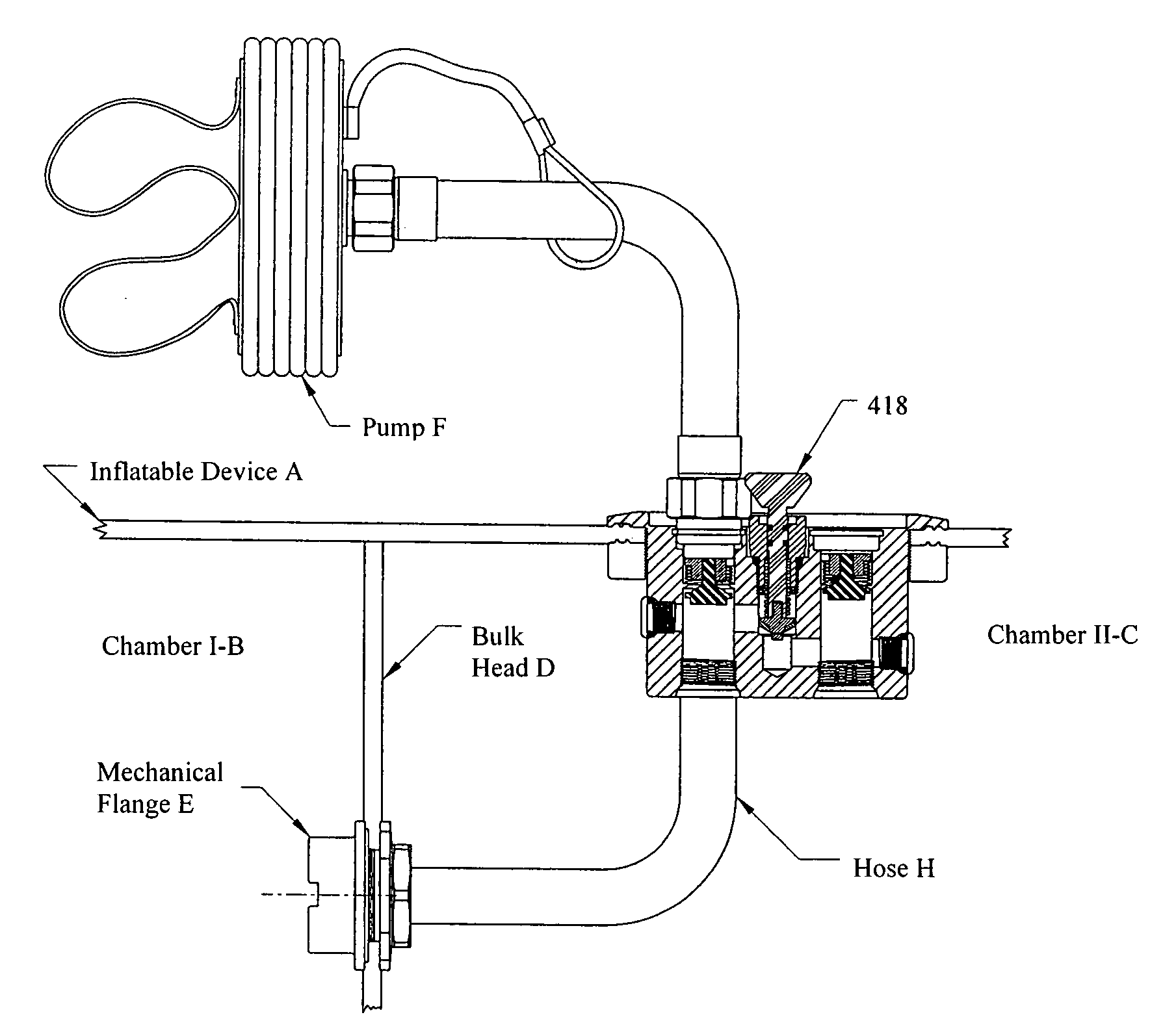
[0078]the internal cross over valve assembly is shown in FIGS. 34–36 and indicated as 400. Internal cross over valve assembly 400 includes a valve body 410, a retainer ring 412, a pair of topping or like valves 414 and 416, a cross over valve 418, and plugs 420.
[0079]Valve body 410 is preferably a unitary valve body of a cylindrical design that includes a circular flange 420 with a sunken recess 422 in the center thereof. Three passages 423, 425 and 427 extend from this recess to an opposite end of the body 410. The valve body includes an outside wall 452 with a threaded portion preferably adjacent the underneath portion of the flange 420 as shown in FIG. 35. This underneath portion of the flange may further include a unique sealing design substantially similar to that described above for the first embodiment that mates with a retainer ring 412 substantially identical to retainer 14 in the first embodiment.
[0080]Passages 423 and 425 are for receiving topping valves 414 and 416 respe...
PUM
 Abstract
Description
Claims
Application Information
 - R&D
- Intellectual Property
- Life Sciences
- Materials
- Tech Scout
- Unparalleled Data Quality
- Higher Quality Content
- 60% Fewer Hallucinations
Browse by: Latest US Patents, China's latest patents, Technical Efficacy Thesaurus, Application Domain, Technology Topic, Popular Technical Reports.
© 2025 PatSnap. All rights reserved.Legal|Privacy policy|Modern Slavery Act Transparency Statement|Sitemap|About US| Contact US: help@patsnap.com


