Mag-tab design for biasing magnetic sensors

a magnetic sensor and magnetic field technology, applied in the field of magnetic sensor stabilization, can solve the problems of reducing sensor efficiency, reducing signal amplitude, data error, etc., and achieve the effect of reducing side-reading and signal amplitude penalties

Inactive Publication Date: 2006-03-21
SEAGATE TECH LLC
View PDF33 Cites 21 Cited by
  • Summary
  • Abstract
  • Description
  • Claims
  • Application Information

AI Technical Summary

Benefits of technology

[0014]A structure for stabilizing a magnetic sensor, which includes a biasing multilayer element having a first end and a second end, wherein the first end abuts the active region of the magnetic sensor. A hard ferromagnetic element is located adjacent to the second end o...

Problems solved by technology

The detection of additional magnetic flux from adjacent tracks or adjacent bit fields leads to errors in the data.
The uniform pinning of the active region over the whole sensor has the advantage of easy processing, but reduces sensor efficiency due to a reduction in signal amplitude because of strong pinning at the center part of the active region.
Pinning of the MR layer using a uniform stabilization across the MR element suppresses the signal amplitude, while at the same time, the pinning strength at the ends of the MR layer may not be strong enough to control domain movement.
However, the pinning strength at the end of the ...

Method used


Image

  • Mag-tab design for biasing magnetic sensors
  • Mag-tab design for biasing magnetic sensors
  • Mag-tab design for biasing magnetic sensors

Examples


Embodiment Construction

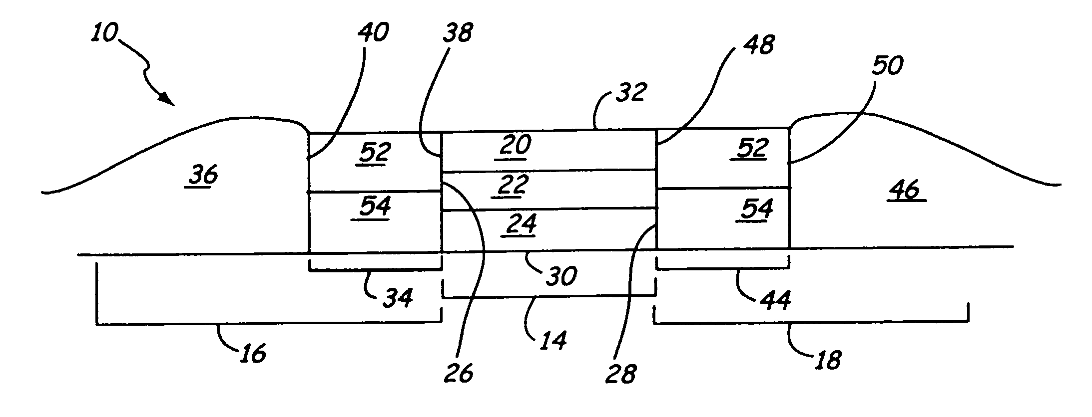
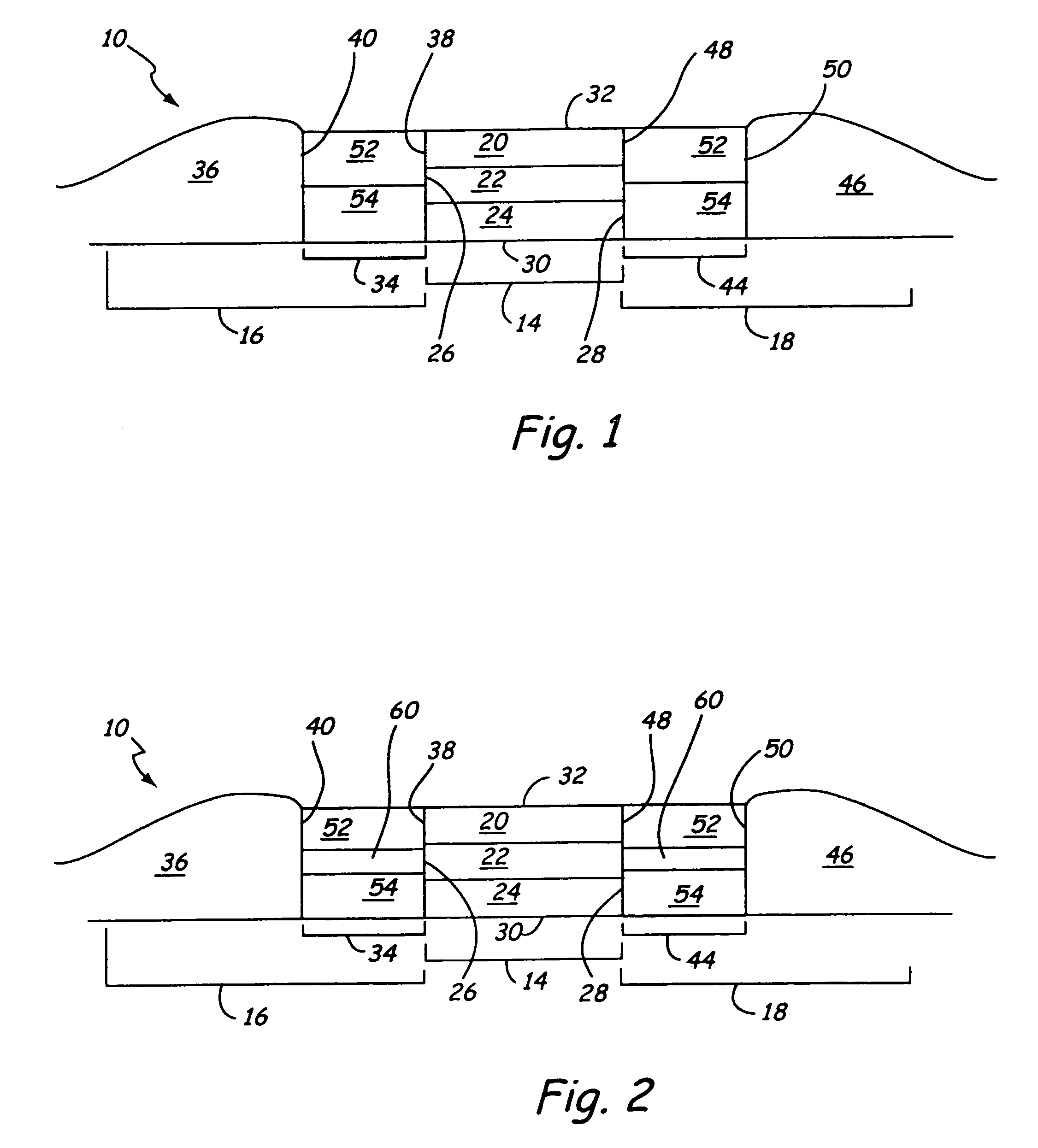
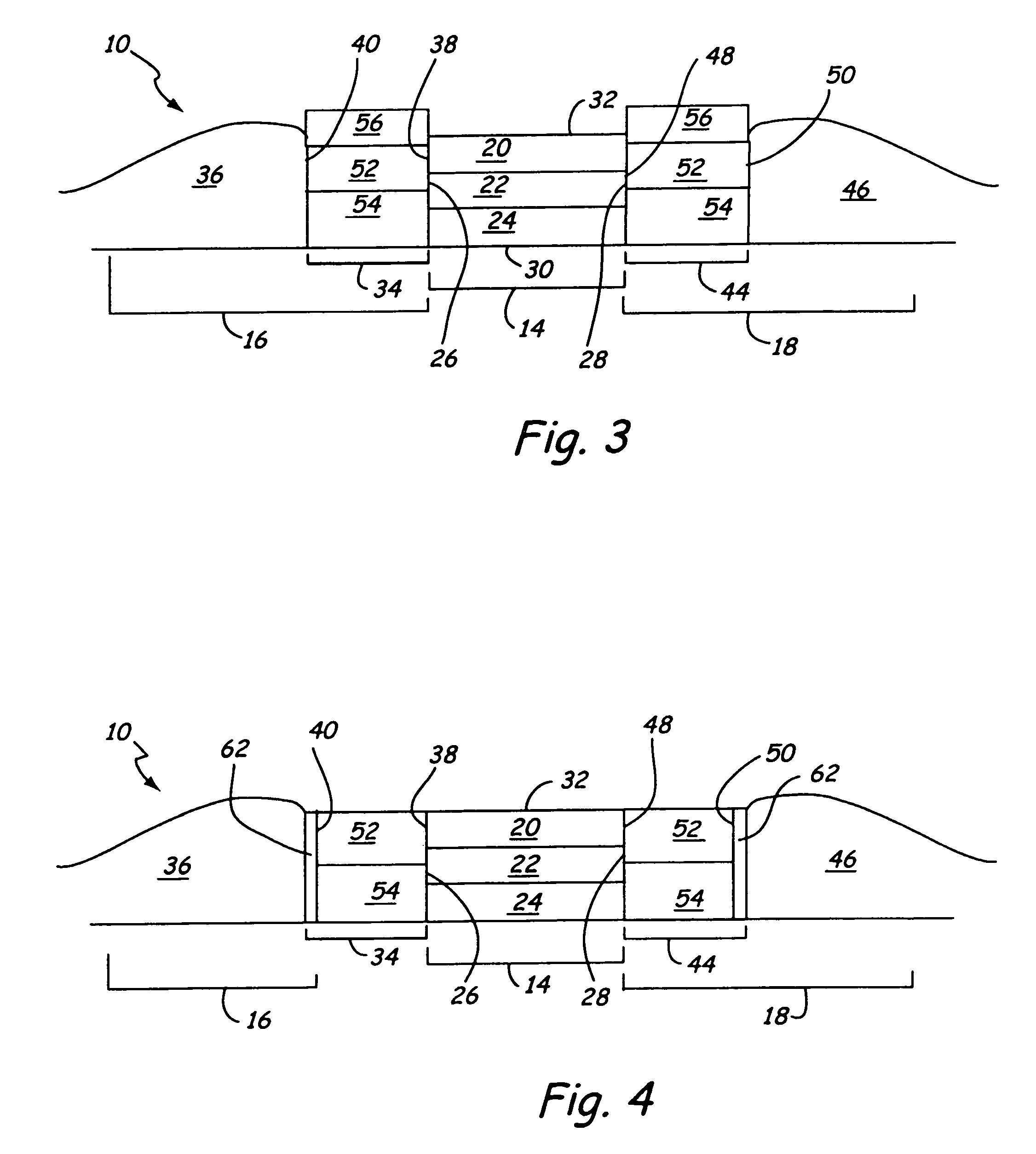
[0019]The stabilization structure of the present invention may be used with various types of magnetic sensors, including but not limited to: MR, GMR and spin valve. An MR or GMR sensor 10 consistent with the present invention is shown in FIG. 1. The MR or GMR sensor 10 includes: a central region 14, a first biasing structure 16 and a second biasing structure 18. The MR or GMR sensor will also include the following additional structures which are not shown in FIG. 1: one or more contacts, and one or more shields (e.g. top and bottom shields) according to the specific sensor design.

[0020]The central region 14 of a MR or GMR sensor 10 is generally a multilayer structure wherein one or more layers are magnetically active and free to respond to changes in magnetic flux. This type of layer is commonly called a free layer or MR layer, and although referred to as a singular layer, the teachings of the present invention are also applicable to sensor designs incorporating multiple MR or GMR l...


PUM


Abstract

A structure for stabilizing the active region of the magnetic sensor comprises a hard ferromagnetic element adjacent to a biasing multilayer element placed on either side of the active region of the magnetic sensor. The biasing multilayer element includes soft ferromagnetic and anti-ferromagnetic layers such that the biasing strength applied to the active region of the magnetic sensor is tuneable by adjusting the length of the soft ferromagnetic layer or layers as well as the insertion of spacer layers between the soft ferromagnetic materials and the anti-ferromagnetic layers. The inventive structure provides longitudinal bias to the active region with improved domain control, signal amplitude and side-reading properties.

Description

CROSS-REFERENCE TO RELATED APPLICATION(S)[0001]This application claims priority from Provisional Application No. 60 / 417,469 filed Oct. 10, 2002 for MAG-TAB DESIGN FOR BIASING MAGNETIC SENSORS of Chunhong Hou, Xuefei Tang, Qing He and Lei Wang.BACKGROUND OF THE INVENTION[0002]The present invention generally relates to the stabilization of the active region of a magnetic sensor for the prevention of Barkhausen noise. More specifically, the invention relates to control of the domains at the ends of the sensing layer without reductions in signal amplitude, while preventing side-reading, thereby enhancing the operation of magnetoresistive sensors.[0003]In the most general terms, a magnetic sensor has an active region containing a sensing layer. The sensing layer is typically a soft ferromagnetic material that responds to changes in magnetic flux. The presence of magnetic flux causes the domains within the soft magnetic material to align with the magnetic field. Therefore, it is desirable...

Claims


Application Information

Patent Timeline
IPC IPC(8): G11B5/127
CPCB82Y10/00B82Y25/00G11B5/3932G01R33/093G11B2005/3996
Inventor HOU, CHUNHONGTANG, XUEFEIHE, QINGWANG, LEI
Owner SEAGATE TECH LLC
Why Eureka
Try Eureka