Address modification within a switching device in a packet-switched network

Active Publication Date: 2006-03-21
ADVANCED MICRO DEVICES INC
View PDF8 Cites 153 Cited by
  • Summary
  • Abstract
  • Description
  • Claims
  • Application Information

AI Technical Summary

Problems solved by technology

Generating and substituting the new MAC destination address for the old MAC address incurs additional overhead for the gateway router that is not experienced

Method used


Image

  • Address modification within a switching device in a packet-switched network
  • Address modification within a switching device in a packet-switched network
  • Address modification within a switching device in a packet-switched network

Examples


Embodiment Construction

[0017]The following detailed description of the invention refers to the accompanying drawings. Like objects in the drawings may be referred to using the same reference numeral in different drawings. The detailed description does not limit the invention. Instead, the scope of the invention is defined by the appended claims and equivalents.

[0018]As described herein, a switch performs layer 3 routing functions, including substituting MAC destination addresses based on a packet's IP address. The MAC address substitution is efficiently handled within the switch using a minimum of additional circuitry relative to previous generations of layer 2 switches.

[0019]Switch Architecture Overview

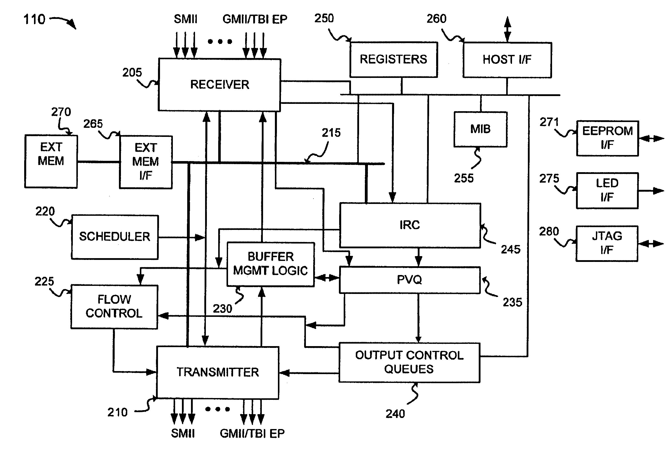
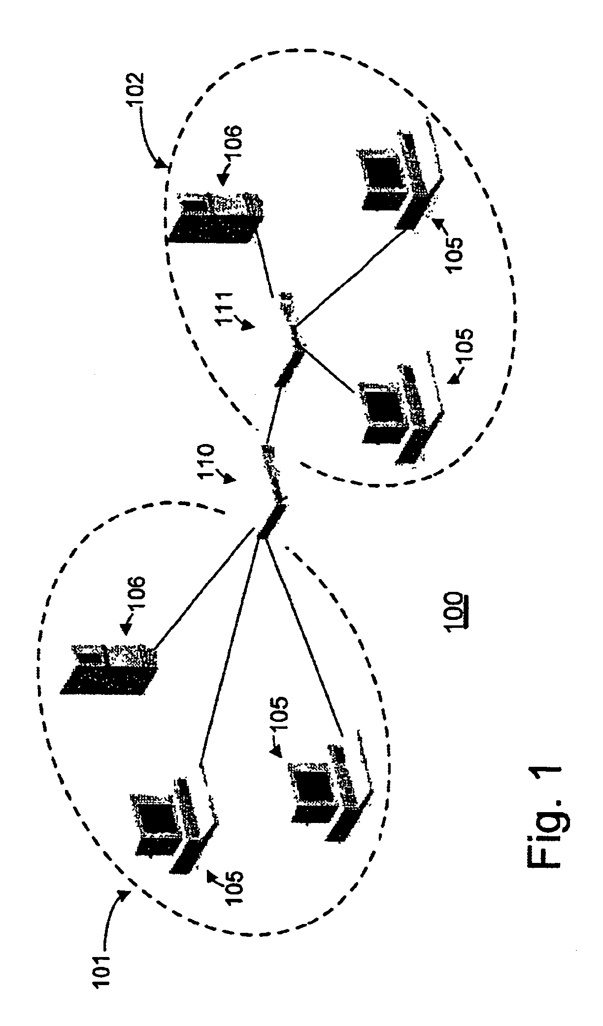
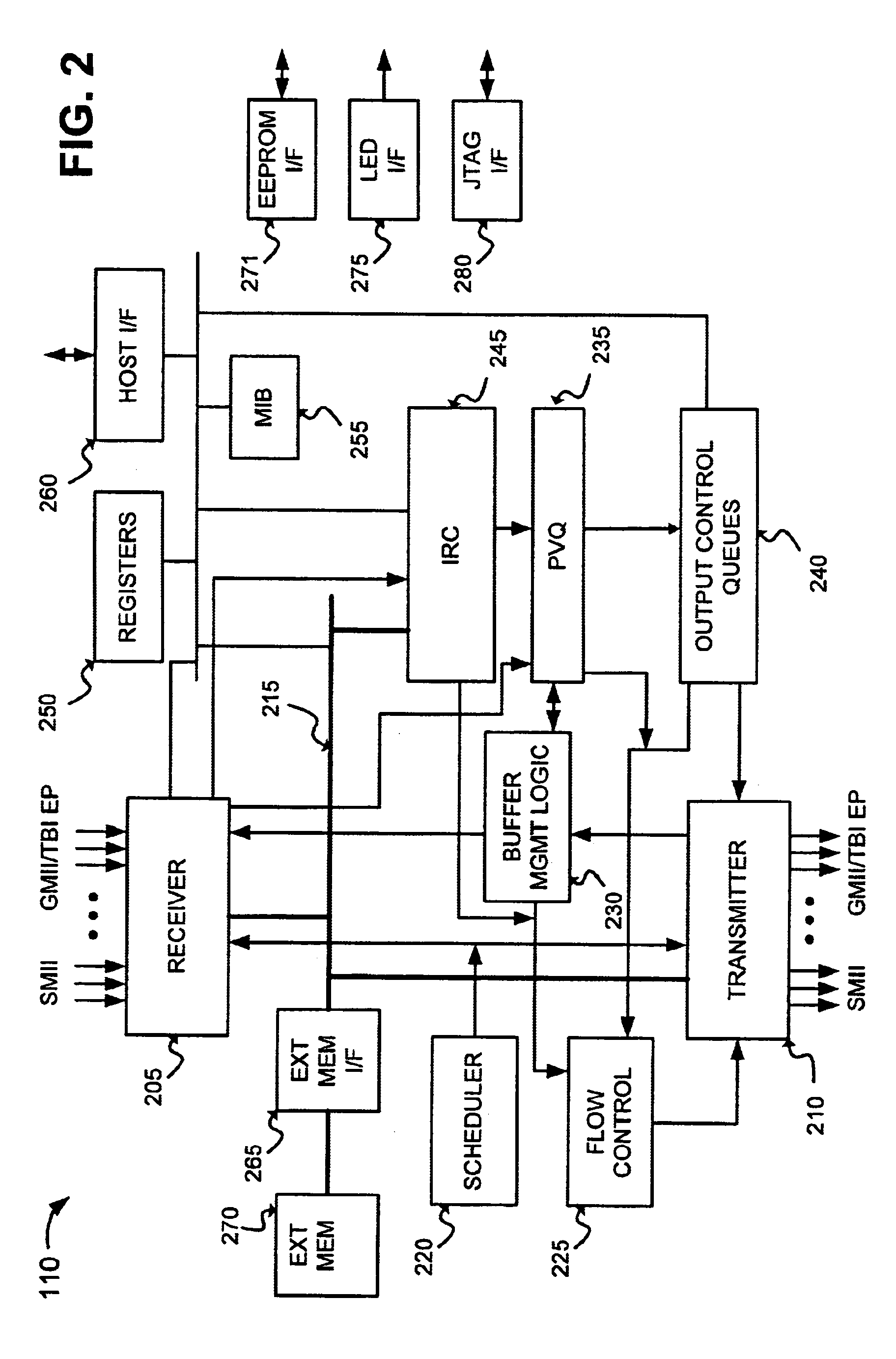
[0020]The present invention will be described with the example of a layer 3 switch or router in a packet switched network, such as an Ethernet (IEEE 802.3) network. It will become apparent, however, that the present invention is also applicable to other types of packet switched systems, as described in det...


PUM


Abstract

A multiport switching device includes an Internal Rules Checker (IRC) that determines forwarding addresses for packets received at the device. The determined forwarding addresses may include a new MAC destination address that is to substituted for the MAC destination address of the received packet. In one implementation, the new MAC destination address is transmitted from the IRC to the dequeuing logic by transmitting pairs of adjacent words through the switch output queues. In other implementations, the new MAC destination address is transmitted from the IRC to the dequeuing logic by transmitting an index field to the output queuing logic or by having the IRC write the new MAC destination address directly to memory.

Description

BACKGROUND OF THE INVENTION[0001]1. Technical Field[0002]The present invention relates generally to switching in a packet switched network and, more specifically, to systems and methods for translating network addresses within a network device.[0003]2. Background Art[0004]At the heart of most networks are switches interconnected via a communications medium. For example, Ethernet is a commonly used local area network scheme in which multiple stations are connected to a single shared serial data path. These stations communicate with a switch located between the shared data path and the stations connected to that path. The switch controls the communication of data packets on the network.[0005]Networks are frequently organized into sub-networks, called subnets. Within a single subnet, packets of information may be directed to their destination devices using a layer 2 Media Access Control (MAC) address that identifies the attached Ethernet devices. When a switch receives a packet with a ...

Claims


Application Information

Patent Timeline
IPC IPC(8): H04L12/28H04L12/56
CPCH04L49/604H04L49/205H04L49/3009
Inventor CHOW, PETER KA-FAIVISWANATH, SOMNATHTZENG, SHR-JIE
Owner ADVANCED MICRO DEVICES INC
Why Eureka
Try Eureka