Support pillow with flaps and methods

a support pillow and flap technology, applied in the field of therapeutic support pillows, can solve the problems of limiting use, inconvenient use, and difficult portability of structures, and achieve the effect of convenient movement and transportation of pillows, convenient removal and replacement of toys

Inactive Publication Date: 2006-03-28
THE BOPPY CO LLC
View PDF86 Cites 81 Cited by
  • Summary
  • Abstract
  • Description
  • Claims
  • Application Information

AI Technical Summary

Benefits of technology

[0024]In a preferable aspect, the pillow includes two or more straps so that a variety of toys may be attached to the pillow. Further, the pillow will preferably be fashioned to include a medial region and first and second arms extending from the medial region to define a generally circular open well. With this arrangement, the straps are attached to the medial region so that a child may lay on the pillow, with the stomach being over the well, and play with the toys that are attached to the pillow. The straps are therefore advantageous in that they hold the toys close to the pillow so that the child will not push the toys out of reach during play.
[0025]The straps may be configured in a variety of ways to hold the toys to the pillow. For example, the toys could be tied to...

Problems solved by technology

Although some support structures have been proposed for supporting objects or body parts, such as the arms of a chair or certain braces, such structures are often uncomfortable and inconvenient to use.
F...

Method used


Image

  • Support pillow with flaps and methods
  • Support pillow with flaps and methods
  • Support pillow with flaps and methods

Examples


Embodiment Construction

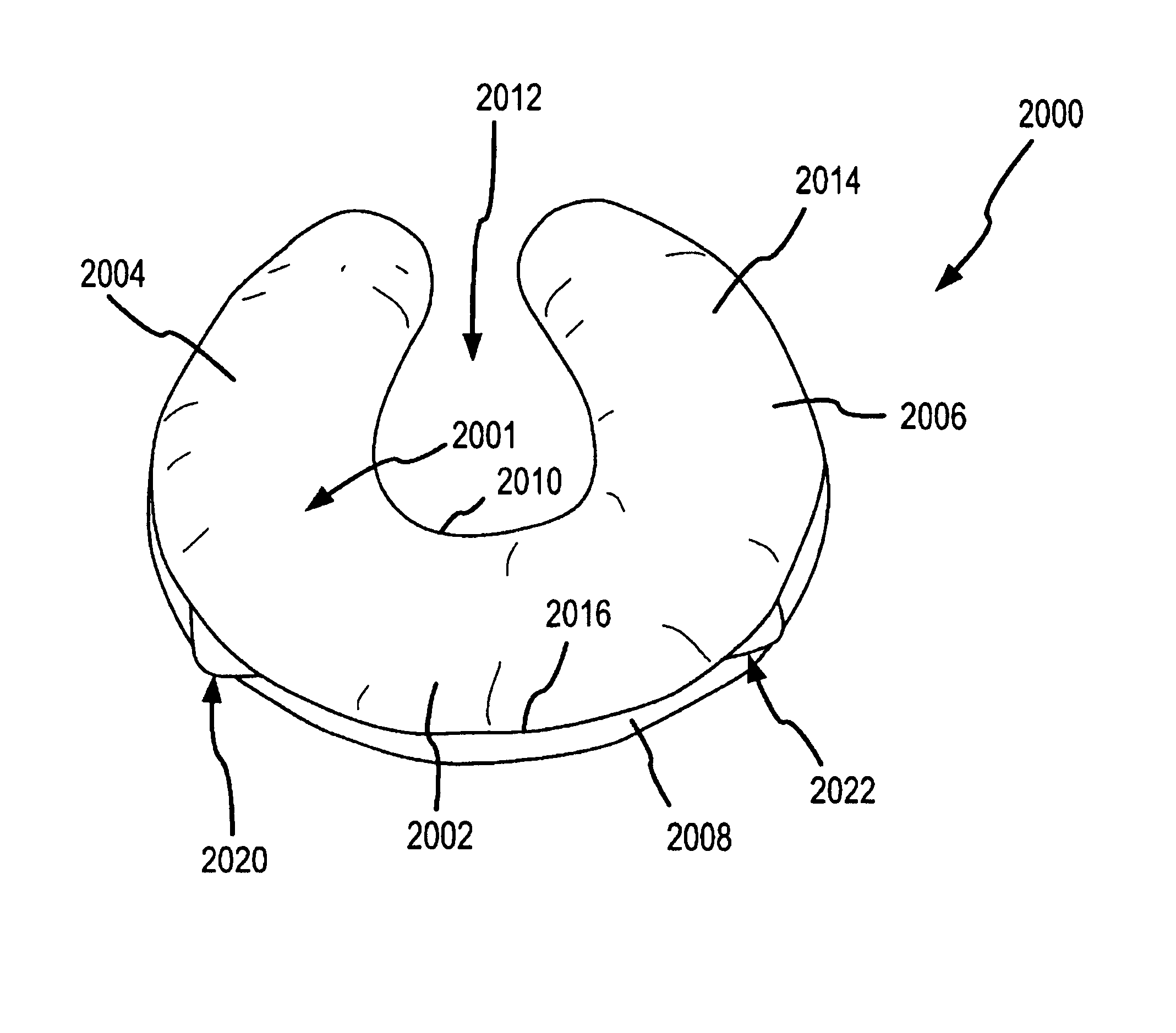
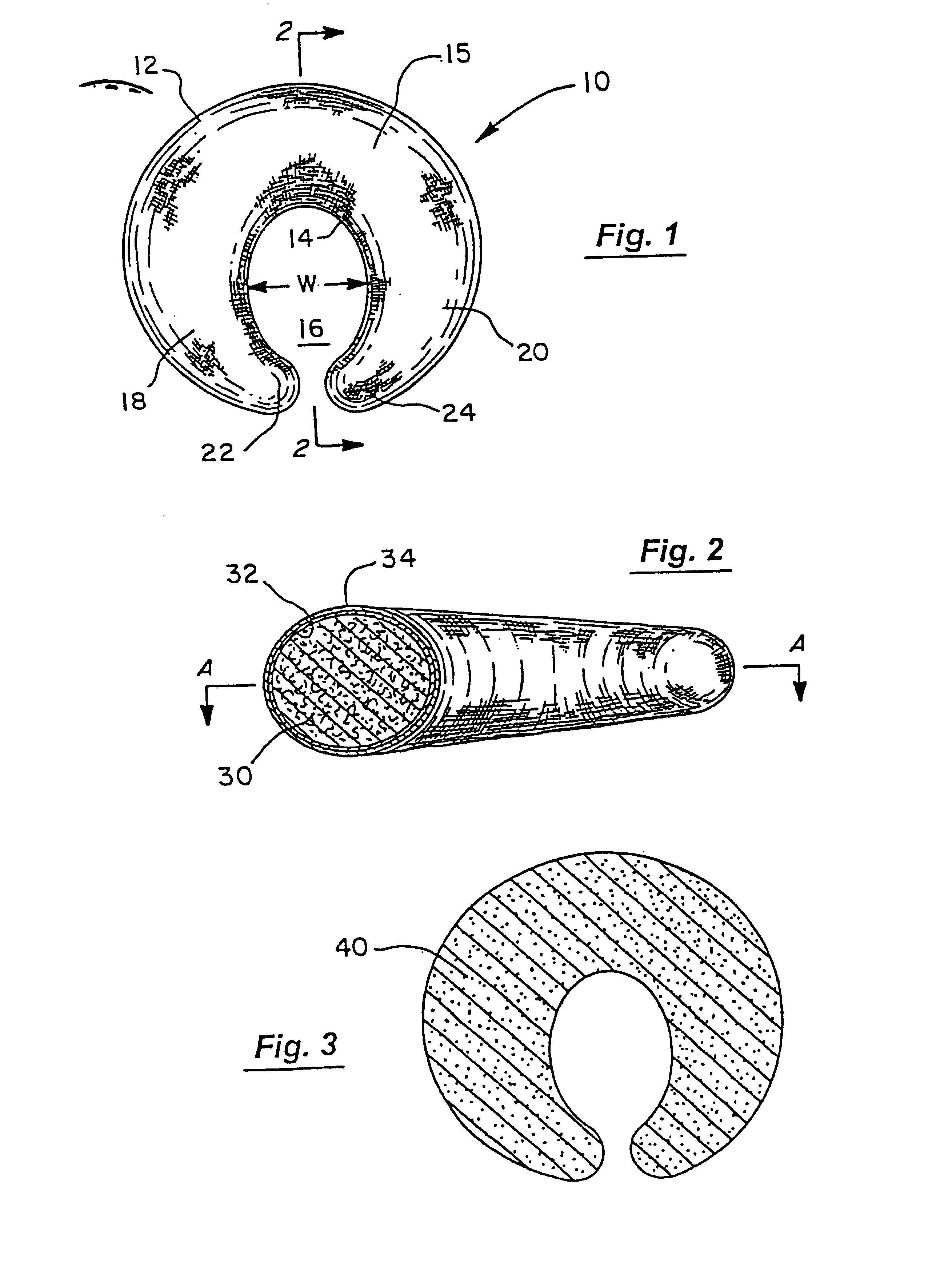
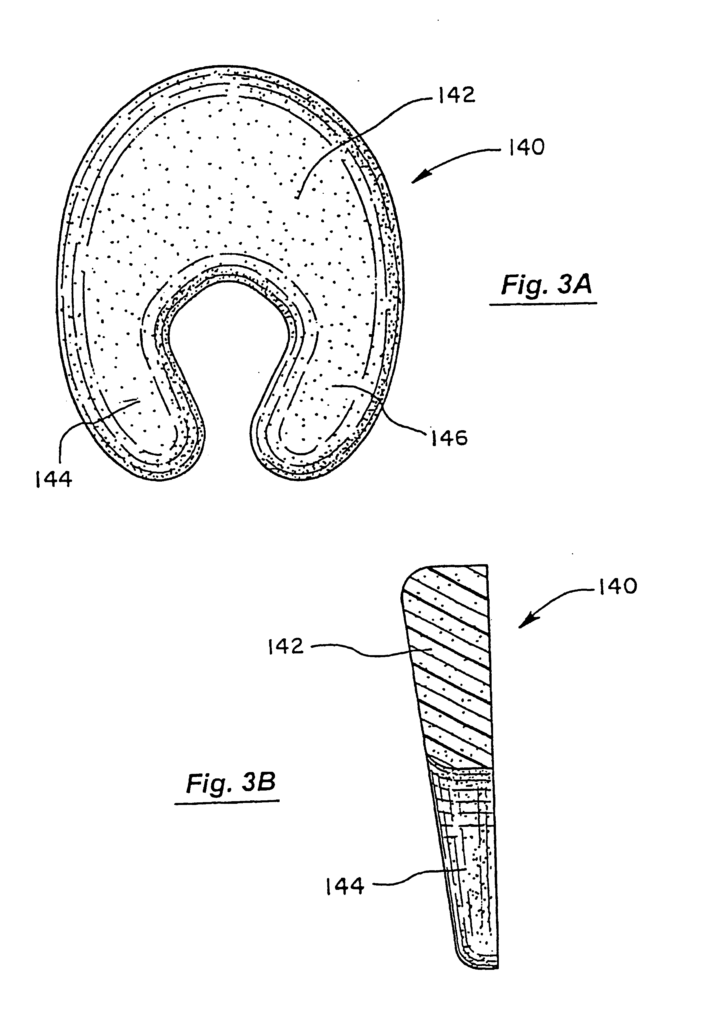
[0053]Referring to FIG. 1, an exemplary embodiment of a support pillow 10 will be described. The support pillow 10 may be constructed similar to the support pillow described in U.S. Pat. No. 5,261,134, as well as in 5,661,861; 6,038,720; 6,055,687; 6,434,770; 6,352,612; 6,279,185; 6,412,128; 6,453,493; and 6,523,200; and in copending U.S. application Ser. No. 10 / 046,377, filed Oct. 26, 2001 (now U.S. Pat. No. 6,671,908), Ser. No. 09,884,742, filed Jun. 18, 2001 (now U.S. Pat. No. 6,640,977), Ser. No. 09 / 679,139, filed Oct. 3, 2000, Ser. No. 09 / 802,097, filed Mar. 8, 2001, 10 / 426,067, filed Apr. 28, 2003 (now U.S. Pat. No. 6763539); and Ser. No. 10 / 612266, filed on Jul. 1, 2003, and Ser. No. 10 / 612267, filed on Jul. 1, 2003 now U.S. Pat. No. 6,857,150. The complete disclosures of all these references are incorporated herein by reference. The support pillow 10 includes a curved outer surface 12 that is rounded in both a longitudinal and a lateral direction. The support pillow 10 furth...


PUM


Abstract

A support pillow comprises a pillow body having a medial region and two opposing arms a pillow body having a medial region and two opposing arms that define an outer periphery and an inner periphery, wherein the inner periphery defines a generally open well. At least one flap is coupled to the pillow body at the outer periphery to adjust the position of the pillow when worn about a user.

Description

CROSS-REFERENCES TO RELATED APPLICATIONS[0001]This application is a continuation in part application of U.S. application Ser. No. 10 / 460,508, filed Jun. 11, 2003 , which is a continuation application of U.S. application Ser. No. 09 / 884,742, filed June 18, 2001 (now U.S. Pat. No. 6,640,977), which is continuation in part application of U.S. application Ser. No. 09 / 537,949, filed Mar. 28, 2000 (now 6,685.024) which is a divisional application of U.S. application Ser. No. 09 / 265,163 (U.S. Pat. No. 6,055,687), which is a divisional application of U.S. application Ser. No. 08 / 831,803, filed Apr. 9,1997 (abandoned), which is a continuation-in-part application of U.S. application No. 08 / 590,653, filed Jan. 24, 1996 (U.S. Pat. No. 5,661,861); and is a continuation is part of U.S. application Ser. No. 10 / 046,377, filed Oct. 26, 2001 (now 6,671,908), the complete disclosures of which are herein incorporated by reference.BACKGROUND OF THE INVENTION[0002]The present invention relates generally ...

Claims


Application Information

Patent Timeline
IPC IPC(8): A47G9/00A47C16/00A47D13/08A47D15/00
CPCA47C7/383A47C7/546A47D15/00A47D13/08A47D13/083A47C16/00
Inventor MATTHEWS BROWN, SUSAN H.
Owner THE BOPPY CO LLC
Why Eureka
Try Eureka