Method and system for automatically optimizing zone duct damper positions

a technology of automatic optimization and duct damper position, which is applied in the direction of ventilation system, heating type, domestic cooling apparatus, etc., can solve the problems of unfavorable airflow, increased noise level in that zone, and increased noise level, so as to reduce actual airflow.

Active Publication Date: 2006-03-28
CARRIER CORP
View PDF6 Cites 127 Cited by
  • Summary
  • Abstract
  • Description
  • Claims
  • Application Information

AI Technical Summary

Problems solved by technology

The damper positions are selected to achieve a desired temperature in that zone, and if additional air is driven through the supply duct into a zone, typically, that zone may become over-conditioned.
In addition, as the amount of air flowing into any one zone increases, the noise level in that zone also increases.
At times, this noise level may become undesirably high.
This solution, however, requires the expense and installation of a bypass valve.
As such, additional problems can arise.

Method used


Image

  • Method and system for automatically optimizing zone duct damper positions
  • Method and system for automatically optimizing zone duct damper positions
  • Method and system for automatically optimizing zone duct damper positions

Examples


Embodiment Construction

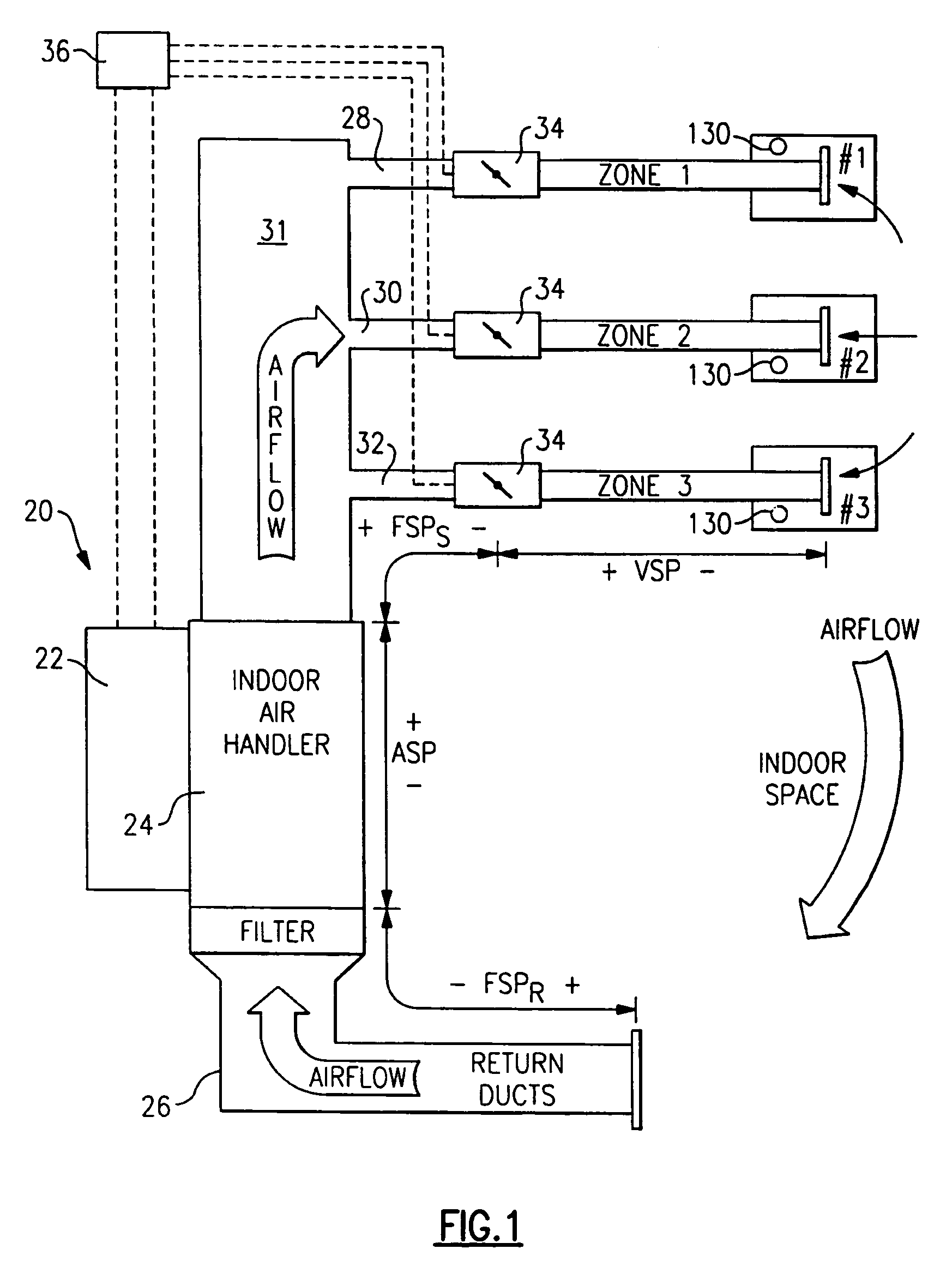
[0017]A multi-zone HVAC system is shown schematically at 20 in FIG. 1. A temperature changing component 22 for changing the condition of air, e.g., an indoor unit (furnace / heater coil) and / or an outdoor unit (air conditioning / heat pump), is associated with an indoor air handler 24. Air handler 24 takes air from return ducts 26 and drives the air into a plenum 31, and a plurality of supply ducts 28, 30, and 32 associated with distinct zones 1, 2, and 3 in a building. As shown, a damper 34 is provided on each of the supply ducts 28, 30 and 32. A control, such as a microprocessor control 36 controls the dampers 34, temperature changing component 22, indoor air handler 24, and also communicates with controls 130 associated with each of the zones. The controls 130 can essentially be thermostats allowing a user to set desired temperature, noise levels, etc. for each of the zones relative to the others. Moreover, the controls 130 preferably include a temperature sensor for providing an act...


PUM


Abstract

A control is functional to perform a method of determining a maximum desired airflow for each of a plurality of zones in a multi-zone HVAC system, and an expected airflow to those zones. In part, these determinations are based upon an algorithm that calculates the relative size of the ducts leading to each of the zones. The expected and maximum airflows are compared for each of the zones, and if any zone has an expected airflow that exceeds its maximum airflow, certain steps are taken to reduce airflow to that zone.

Description

[0001]This application claims priority to provisional patent application Ser. No. 60 / 537,717, filed Jan. 20, 2004 and entitled “Method and System for Automatically Optimizing Zone Duct Damper Positions.” The disclosure of this provisional application is incorporated herein in its entirety, by reference.BACKGROUND OF THE INVENTION[0002]This application relates to a method and system for adjusting the position of the zone dampers in a multi-zone heating, ventilating and air conditioning (HVAC) system to ensure that unduly high levels of air do not flow into any of the zones.[0003]Multi-zone HVAC systems are known, and include a component(s) for changing the temperature and condition of air (a furnace, air conditioner, heat pump, etc.). For simplicity, these components will be referred to collectively as a temperature changing component. Also, an indoor air handler drives air from the temperature changing component through supply ducts to several zones within a building. Each of the su...

Claims


Application Information

Patent Timeline
Patent Type & Authority Patents(United States)
IPC IPC(8): F24F7/00G05B13/02F24F3/044F24F13/02
CPCF24F3/0442F24F11/0076G05D23/1934F24F13/02Y02B30/767F24F11/70
Inventor SHAH, RAJENDRA K.VANOSTRAND, WILLIAM F.WERBOWSKY, LAURIE L.
Owner CARRIER CORP
Why Eureka
Try Eureka