Trailer coupler

a technology of couplers and trailers, applied in the field of trailer couplers, can solve the problems of user making theft of load more difficult, third parties not being able to secure, etc., and achieve the effects of easy assembly and coupling to the ball hitch, not compromising coupler strength or security

Inactive Publication Date: 2006-03-28
BONFANTI DOMINIC S
View PDF10 Cites 12 Cited by
  • Summary
  • Abstract
  • Description
  • Claims
  • Application Information

AI Technical Summary

Benefits of technology

[0012]A ball hitch coupler for use with a towing vehicle having a ball hitch. The ball hitch coupler provides an improved and simplified structure designed to make assembly and coupling to the ball hitch easy, while not compromising coupler strength or security. The ball hitch coupler comprises a coupler housing having a ball hitch cavity, a locking passageway also located in the coupler housing, and a locking rod having a keyed section.
[0013]In operation, the ball hitch, typically located toward the rear of the towing vehicle, is situated within the coupler housing by sliding the ball section on the ball hitch into the ball hitch cavity which is configured and positioned to receive the ball hitch. The locking rod is then inserted into the locking passageway which is located in the coupler housing and sized and configured to releasably receive the locking rod. In its inserted and secured position, the locking rod protrudes into the ball hitch cavity, in a position adjacent to the ball section on the ball hitch, to physically restrain the movement of the ball section within the ball hitch cavity. In its secured and fully inserted position within the locking passageway, the locking rod prevents the removal of the ball hitch from the ball hitch cavity, thereby securing the coupling of the coupler housing to the ball hitch.
[0014]In addition to operating as a restraining mechanism to secu

Problems solved by technology

Therefore, without the keyed locking rod, third parties will not be able to secure a load having the ball hitch coupler to their vehicles.
Thus, th

Method used


Image

  • Trailer coupler
  • Trailer coupler
  • Trailer coupler

Examples


Embodiment Construction

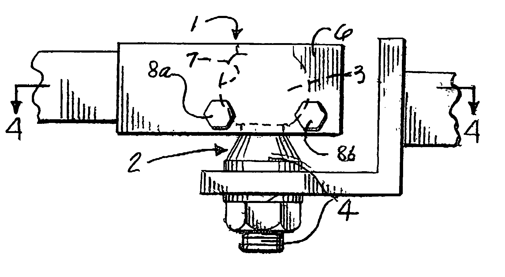
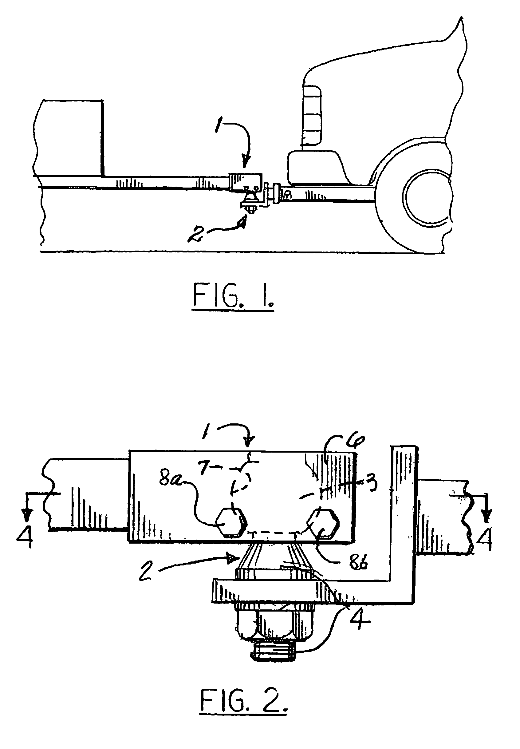
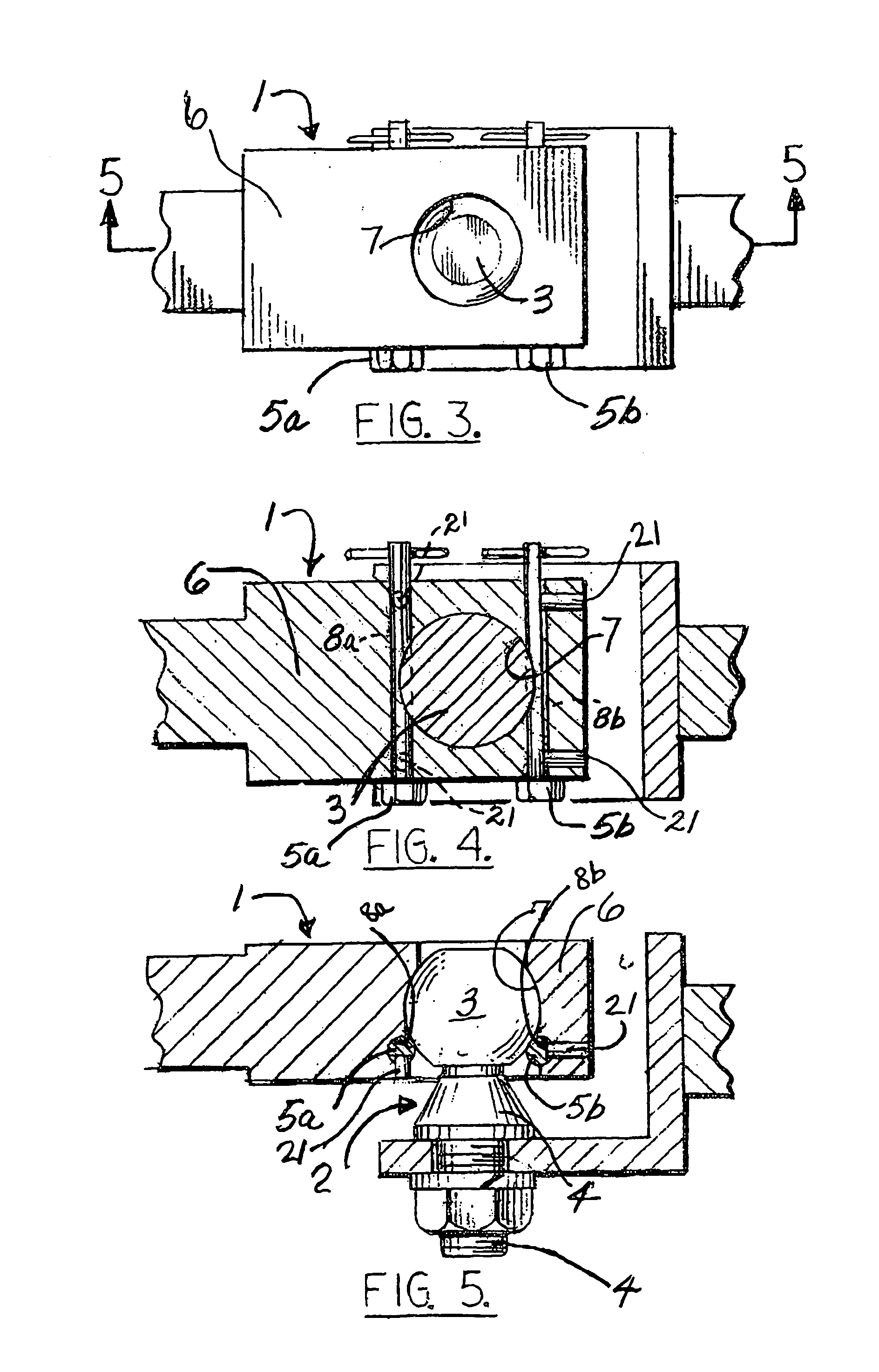
[0030]A ball hitch coupler 1, for use with a towing vehicle having a ball hitch 2, is disclosed. Ball hitch 2 comprises a ball section 3 mounted on a shaft section 4. Ball hitch coupler 1 comprises a coupler housing 6 having a ball hitch cavity 7, a locking passageway 8 also located in coupler housing 6, and a locking rod 5. Locking rod 5 further comprises a first end 9, a second end 10, a longitudinal axis extending therebetween 11, and a keyed section 12 having a cross section 22 perpendicular to longitudinal axis 11. In an alternative preferred embodiment of the invention, ball hitch coupler 1 further comprises a second locking passageway 8b located in coupler housing 6 and a second locking rod 5b. Second locking rod 5b further comprises first end 9, second end 10, longitudinal axis extending therebetween 11, and a keyed section 12 having cross section 22 perpendicular to longitudinal axis 11.

[0031]In operation, ball hitch 2, typically located toward the rear of the towing vehicl...


PUM


Abstract

A ball hitch coupler for use with a towing vehicle having a ball hitch. The ball hitch coupler provides an improved and simplified structure designed to make assembly and coupling to the ball hitch easy, while not compromising coupler strength or security. The ball hitch coupler comprises a coupler housing having a ball hitch cavity, a locking passageway also located in the coupler housing, and a locking rod having a keyed section. The locking rod operates as a restraining mechanism to hold the ball hitch within the ball hitch cavity, thereby resulting in a secure coupling of the ball hitch with the ball hitch coupler. In addition, the locking rod, in conjunction with the locking passageway, also serves as a theft protection feature by operating as an inherent lock-key mechanism.

Description

A. BACKGROUND OF THE INVENTION[0001]1. Field of the Invention[0002]This invention relates to trailer couplers in general and to ball hitch couplers in particular.[0003]2. Prior Art[0004]Ball hitch couplers used to connect a towing vehicle to trailers, mobile homes, etc. are well known in the prior art, however there remains a need for their improvement. In the prior art, many hitch couplers are complex structures containing numerous adjustable elements, and lack of expertise on the part of the user often results in improper assembly of the coupler and makes coupling to the ball hitch difficult. Such couplers also have increased manufacturing costs due to their complexity. In addition, may prior art couplers, even when properly assembled and coupled to the ball hitch, contain exposed elements that are subject to damage. Also, many prior art ball hitch couplers are not safe nor reliable as they tend to inadvertently release the ball hitch and therefore, do not provide for a secure cou...

Claims


Application Information

Patent Timeline
IPC IPC(8): B60D1/06
CPCB60D1/28B60D1/065
Inventor BONFANTI, DOMINIC S.
Owner BONFANTI DOMINIC S
Why Eureka
Try Eureka