Constant ON-time controller for a buck converter

a controller and converter technology, applied in the direction of dc-dc conversion, power conversion systems, instruments, etc., can solve the problems stability and susceptibility to noise, and the disadvantage of constant on-time controllers only becomes apparent, so as to reduce the noise susceptibility of inputs

Active Publication Date: 2006-03-28
ANALOG DEVICES INC
View PDF5 Cites 68 Cited by
  • Summary
  • Abstract
  • Description
  • Claims
  • Application Information

AI Technical Summary

Benefits of technology

[0023]A voltage ramp is first replicated generating a first and a second ramp that are substantially equal. The voltage ramps are converted to current ramps with transconductance amplifiers. The output voltage is isolated with a voltage follower and coupled to a series resistor. The reference voltage for the buck regulator is likewise coupled to a series resistor. One of the current ramps is coupled to one side of each of the series resistors. A modified output voltage has one of the ramps superimposed and a modified reference voltage has the other ramp superimposed. The modified output voltage and the modified reference voltage are compared to determine when to start the ON-time of the buck converter. The superimposed ramps reduce the noise susceptibility of the inputs of the comparator while subtracting their offset effect. The ON-time is stopped in response to charging a capacitor with a current proportional to the regulator input voltage.

Problems solved by technology

This creates two problems for constant ON-time controllers, stability and susceptibility to noise.
The disadvantage of constant ON-time controllers only becomes apparent when the ESR 102 of C 101 becomes very small.
The jitter is not a sign of instability, but rather it has the effect of generating uncontrolled voltage ripple on Vout 116 and is therefore undesirable.
Stability is the major problem with constant ON-time controllers in applications using low ESR capacitors.
This zero needs to be introduced into the control loop at a frequency well before the unity gain crossover frequency or the control loop will be unstable.
Eventually too much phase shift occurs in the loop response and the control loop becomes unstable.
An unstable control loop may over react to a transient load step and cause the current in L 104 to overshoot resulting in excessive ringing.
If a significant number of these low ESR ceramic capacitors are used (paralleled) to make C 101, the control loop may become unstable.
While adding an artificially generated ramp has advantages, designing GMA 428 to have the desired bandwidth characteristics and dealing with offsets presents difficulties.

Method used


Image

  • Constant ON-time controller for a buck converter
  • Constant ON-time controller for a buck converter
  • Constant ON-time controller for a buck converter

Examples


Embodiment Construction

[0036]In the following description, numerous specific details are set forth to provide a thorough understanding of the present invention. However, it will be obvious to those skilled in the art that the present invention may be practiced without such specific details. In other instances, well-known circuits may be shown in block diagram form in order not to obscure the present invention in unnecessary detail. For the most part, details concerning timing considerations and the like have been omitted inasmuch as such details are not necessary to obtain a complete understanding of the present invention and are within the skills of persons of ordinary skill in the relevant art.

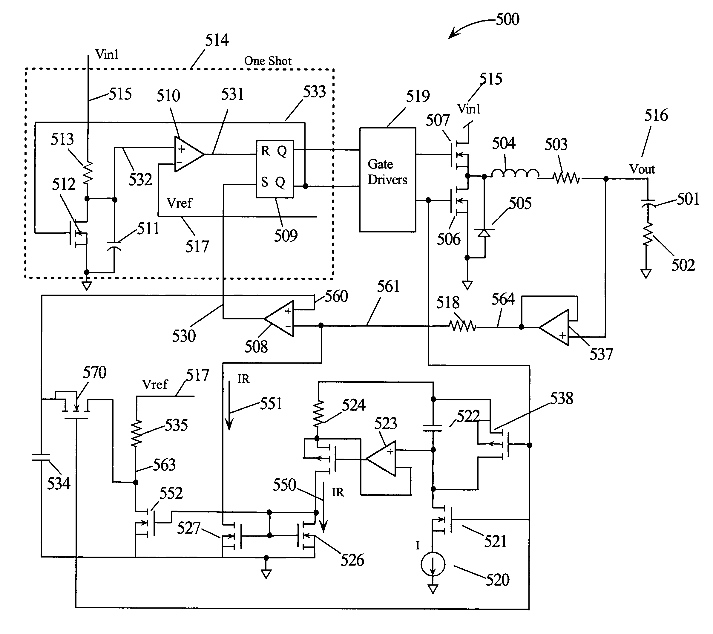
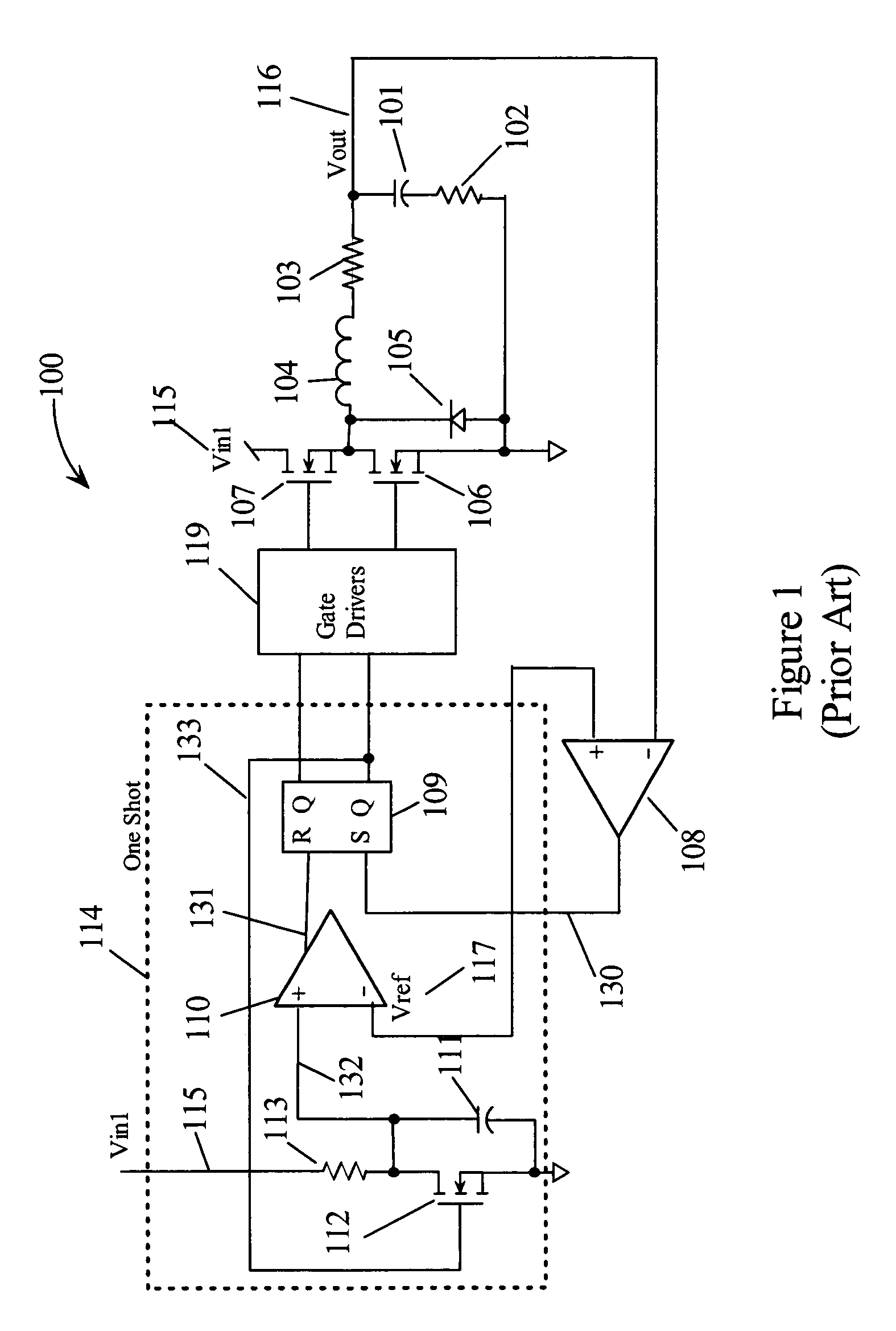
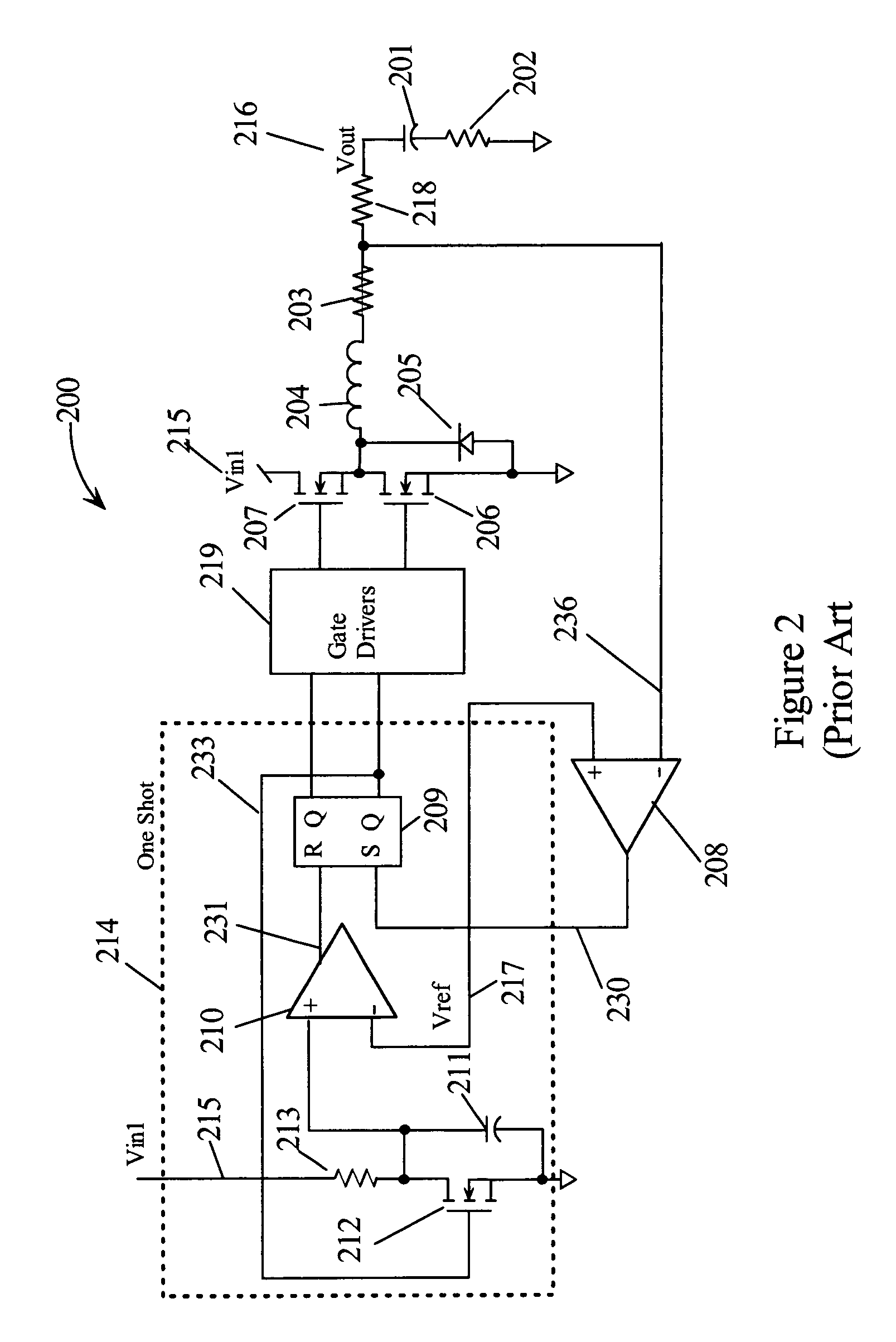
[0037]Refer now to the drawings wherein depicted elements are not necessarily shown to scale and wherein like or similar elements are designated by the same reference numeral through the several views. In the following, buck regulator or buck converter may be used interchangeably. Constant ON-time converters refer...


PUM


Abstract

A constant ON-time controller for a buck converter utilizes dual symmetrical ramps. The ramps may be generated artificially or by sensing the voltage across a sense resistor in the output. The ramp may also be generated by sensing the voltage across the “ON” resistance of the low side FET in the switching regulator. A modified output voltage has one of the ramps superimposed and a modified reference voltage has the other ramps superimposed. The modified output voltage and the modified reference voltage are compared to determine when to start the ON-time of the buck converter. The dual ramps reduce, noise susceptibility. The ON-time is stopped in response to charging a capacitor with the regulator input voltage. An offset may also be generated representing the difference between the average output voltage and the reference voltage. The offset is used to generate a modified reference to compensate for the offset.

Description

TECHNICAL FIELD[0001]The present invention relates in general to controllers for switching regulators and in particular to controllers that set a relatively constant ON-time for the switching devices.BACKGROUND INFORMATION[0002]Constant ON-time controllers are a class of buck regulators that use the output voltage ripple to initiate an ON-time whenever the output voltage falls below the reference voltage. The ON-time is terminated (generating an ON-time pulse) by circuitry in response to other conditions (e.g., level of regulator input). During the ON-time pulse, energy is supplied directly from the regulator input to the output via an electronic switching device. Likewise, when the ON-time pulse has terminated stored energy from the regulator input is supplied to the output. Most constant ON-time regulators include circuits to adjust the ON-time pulse duration as a function of the input and output voltages, thus resulting in an almost constant frequency as the duty cycle changes. T...

Claims


Application Information

Patent Timeline
Patent Type & Authority Patents(United States)
IPC IPC(8): G05F1/56H02M3/156
CPCH02M3/156
Inventor PULLEN, STUARTGROOM, TERRY J.
Owner ANALOG DEVICES INC
Why Eureka
Try Eureka