Method for finding the position of a subscriber in a radio communications system

Active Publication Date: 2006-03-28
RPX CORP +1
View PDF14 Cites 122 Cited by
  • Summary
  • Abstract
  • Description
  • Claims
  • Application Information

AI Technical Summary

Benefits of technology

[0007]One possible object of the present invention is therefore to specify a cost-effective method for finding the position of a sought s

Problems solved by technology

However, a method such as this cannot be used in the radio communications system as described above, in which base stations are used with sp

Method used


Image

  • Method for finding the position of a subscriber in a radio communications system
  • Method for finding the position of a subscriber in a radio communications system

Examples


Example

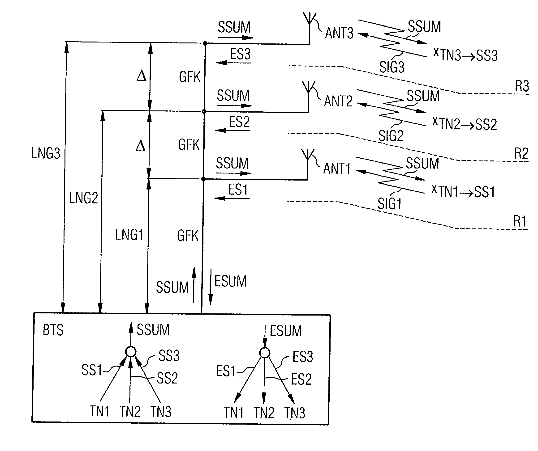
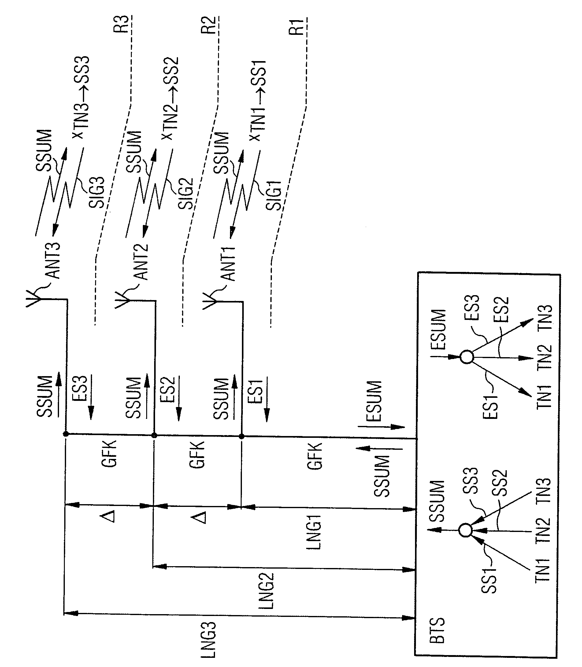
[0012]In the following text, glass fiber cables GFK are used for signal transmission between the base station BTS and the three antenna devices ANT1 to ANT3.

[0013]In the base station BTS, and transmission signals SS1 from a first subscriber TN1 are combined with a transmission signal SS2 from a second subscriber TN2 and with a transmission signal SS3 from a third subscriber TN3 to form a transmission sum signal SSUM. The transmission sum signal SSUM is passed via a glass fiber cable GFK to all three-antenna devices ANT1 to ANT3 for transmission.

[0014]In this case, a first antenna device ANT1, for example in an indoor radio communications system, is assigned a first area R1 of a building G for its radio supply, in which the first subscriber TN1 is located. In a corresponding manner, a second and a third antenna device ANT2 and ANT3, respectively, are assigned to a second and a third area R2 and R3, respectively, for providing the radio supply to the second and third subscriber TN2 an...


PUM


Abstract

A method for finding the position of a subscriber in a radio communications system combines transmission signals from subscribers to form a transmission sum signal, which is passed by cables from a base station to at least two antenna devices for transmission. Received signals from subscribers are received via the antenna devices and are combined to form a received sum signal, which is passed by cables to the base station. Each individual antenna device is associated with an individual area for the radio supply for the subscribers there. Cables lengths, which are used for signal transmission, for each antenna device are chosen individually such that a round trip delay time measurement which is based on the transmission signal and received signal of a sought subscriber is used to determine an antenna device via which the received signal sought subscriber is received. The position of the sought subscriber is determined via the area which is supplied by radio and is associated with the determined antenna device.

Description

CROSS REFERENCE TO RELATED APPLICATIONS[0001]This application is based on and hereby claims priority to German Application No. 10305091.4 filed Feb. 7, 2003 and European Application No. 03002821.1 filed Feb. 7, 2003, the contents of which are hereby incorporated by reference.BACKGROUND OF THE INVENTION[0002]One possible aspect of the invention relates to a method for finding the position of a subscriber in a radio communications system.[0003]In radio communications systems, arrangements with base stations and antenna devices are known, in which transmission signals from two or more subscribers are combined to form a transmission sum signal, and this transmission sum signal is passed by cables from the base station to at least two spatially distributed antenna devices for transmission. On the other hand, radio received signals from subscribers, which are received via the antenna devices, are combined to form a received sum signal, which is transmitted by cables to the base station.[0...

Claims


Application Information

Patent Timeline
IPC IPC(8): H04Q7/20G01S13/87G01S19/09G01S19/46
CPCG01S13/878
Inventor SPLETT, ARMIN
Owner RPX CORP
Why Eureka
Try Eureka