
Even-flow septic tee arrangement

a septic tank and septic tank technology, applied in the direction of filtration separation, lighting and heating equipment, separation processes, etc., can solve the problems of early saturation of the associated leaching field, unbalanced flow transfer out to the distribution pipe,

Inactive Publication Date: 2006-04-04
BURROWS KENNETH +1
View PDF17 Cites 13 Cited by
  • Summary
  • Abstract
  • Description
  • Claims
  • Application Information

AI Technical Summary

Benefits of technology

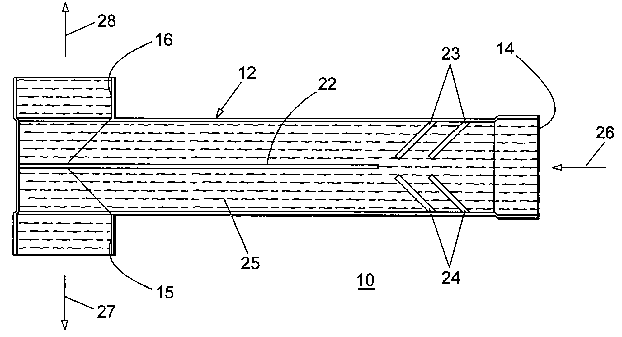
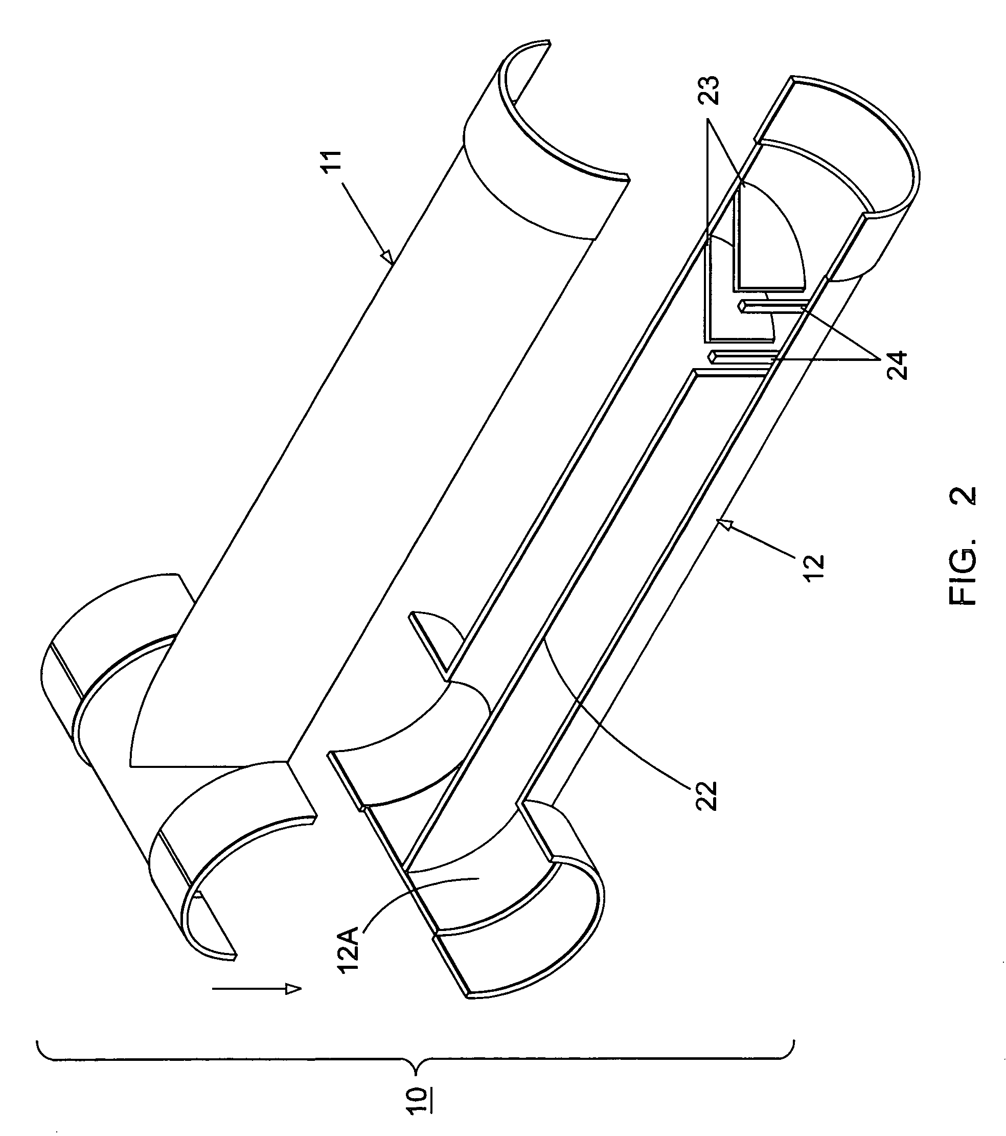
"The patent describes a device called an even-flow tee arrangement that is used in septic systems. It consists of a tee connector with two sections that are cemented together. The bottom section has a splitter plate with directional vanes that help to evenly distribute the fluid flow through the tee. This helps to ensure that the fluid is evenly distributed outwards through the tee-shaped exit. The technical effect of this device is to improve the efficiency and effectiveness of septic systems by ensuring that the fluid is evenly distributed and flows properly through the system."

Problems solved by technology

When a tee connection is employed, there is a tendency for the tee to become slightly rotated such that one side of the tee is lower than the other side causing unequal flow transfer out to the distribution pipes.
The distribution pipe connecting with the lower side of the tee often causes early saturation of the associated leaching field and under-utilization of the distribution pipe connecting with the opposite side thereof.

Method used


Image

  • Even-flow septic tee arrangement
  • Even-flow septic tee arrangement
  • Even-flow septic tee arrangement

Examples


Embodiment Construction

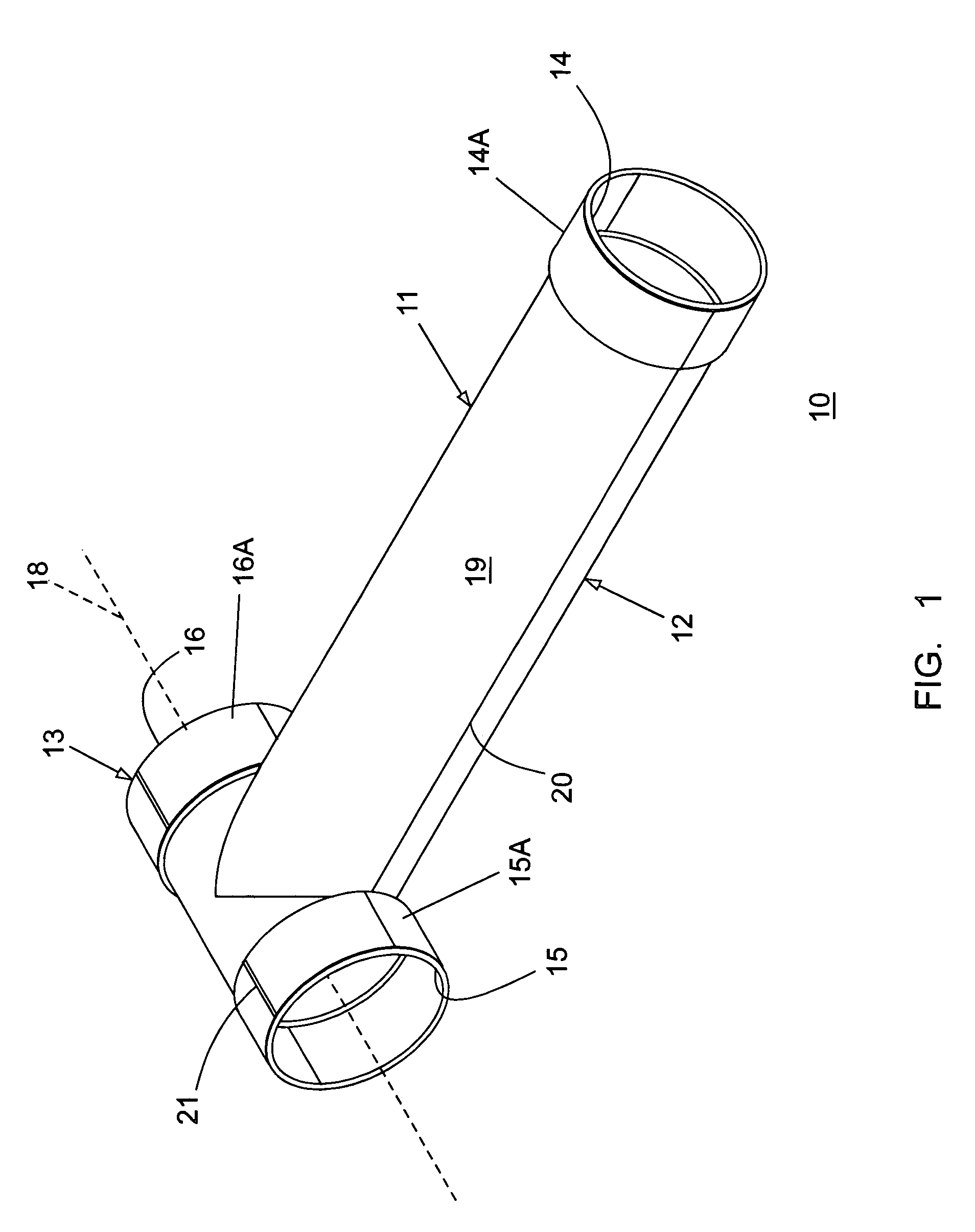
[0011]The even-flow septic tee 10 shown in FIGS. 1 and 2 consists of a top plate 11 and bottom plate 12 made of pvc (polyvinyl chloride) plastic material defining a tee-shaped outlet 13 at one end and a circular inlet opening 14 at the opposite end thereof. A level line 21 is formed on the top of the tee-shaped outlet 13 to assist in aligning the even-flow septic tee 10 with respect to the parallel plane 18, during installation.

[0012]The elongated even-flow septic tee 10 defines a linear section 19 roughly twice the length of the tee-shaped outlet 13 when the top and bottom plates 11, 12 are cemented together, as indicated at 20. The tee-shaped outlet 13 includes opposite side openings 15, 16 for fluid transfer out from the even-flow septic tee 10 in the manner to be described below in greater detail. Each of the openings 14–16 has enlarged collars 14A–16A for attachment with inlet and outlet piping as described in the aforementioned U.S. Pat. No. 6,012,871.

[0013]In accordance with ...


PUM

PropertyMeasurementUnit
lengthaaaaaaaaaa

Abstract

An even-flow tee arrangement for use with a septic system consists of a tee connector having top and bottom section cemented together. The bottom section includes a splitter plate extending from the tee-shaped exit end to two pairs of directional vanes proximate the entrance end of the tee connector.

Description

BACKGROUND OF THE INVENTION[0001]Septic systems of the type connecting a septic holding tank to a distribution field often employ a tee connector between the holding tank and the perforated pipes leading to the leaching field. Other systems utilize a complex interface connection box intermediate the holding tank and the leaching field.[0002]U.S. Pat. No. 4,838,731 entitled “Septic Tank Distribution System” describes an interface box connecting between the tank and leaching field.[0003]U.S. Pat. No. 6,012,871 entitled “Septic Tank System and Distribution System Suitable for Use in Sloping Terrain” describes a tee connection between the tank and the leaching field, for example.[0004]When a tee connection is employed, there is a tendency for the tee to become slightly rotated such that one side of the tee is lower than the other side causing unequal flow transfer out to the distribution pipes. The distribution pipe connecting with the lower side of the tee often causes early saturation...

Claims


Application Information

Patent Timeline
Patent Type & Authority Patents(United States)
IPC IPC(8): F15D1/00F15D1/02F16L41/02
CPCF16L41/021F15D1/02
Inventor BURROWS, KENNETHSATISH, MYSORE G.
Owner BURROWS KENNETH
Learn More