Shoulder belt height adjuster assembly and method

a technology of height adjustment and shoulder belt, which is applied in the direction of pedestrian/occupant safety arrangement, vehicular safety arrangement, safety belt, etc., can solve the problems of reducing the integrity of parts, limiting the number of height adjustment positions, and relatively small adjustment positions

Active Publication Date: 2006-04-04
FCA US
View PDF18 Cites 19 Cited by
  • Summary
  • Abstract
  • Description
  • Claims
  • Application Information

AI Technical Summary

Benefits of technology

[0007]One aspect of the present invention provides a shoulder belt height adjuster assembly. The assembly includes a guide rail, a slide, and a biasing member. The guide rail includes a plurality of fixed rail teeth disposed along at least one longitudinal portion. The slide includes an aperture formed therein for slidably receiving the guide rail along the longitudinal portion. The slide further includes a plurality of fixed slide teeth disposed on an interior slide surface. The biasing member is operably attached to the slide aperture for selectively engaging at least one of the fixed slide teeth into at least one of the fixed rail teeth. The engagement prevents slidable movement of the slide relative to the guide rail in a downward direction.

Problems solved by technology

As such, a plurality of discrete locking positions are provided, but the number of height adjustment positions is limited to the number of the openings.
Although such patents disclose strategies that may effectively provide shoulder belt height adjustment, they typically provide a relatively small number of adjustment positions.
It is possible to increase the number of engagement openings, however, this may reduce the integrity of the parts and / or increase the complexity and cost of the belt assembly.
The use of such auxiliary moveable parts may increase the complexity, cost, and failure rate of the assembly.

Method used


Image

  • Shoulder belt height adjuster assembly and method
  • Shoulder belt height adjuster assembly and method
  • Shoulder belt height adjuster assembly and method

Examples


Embodiment Construction

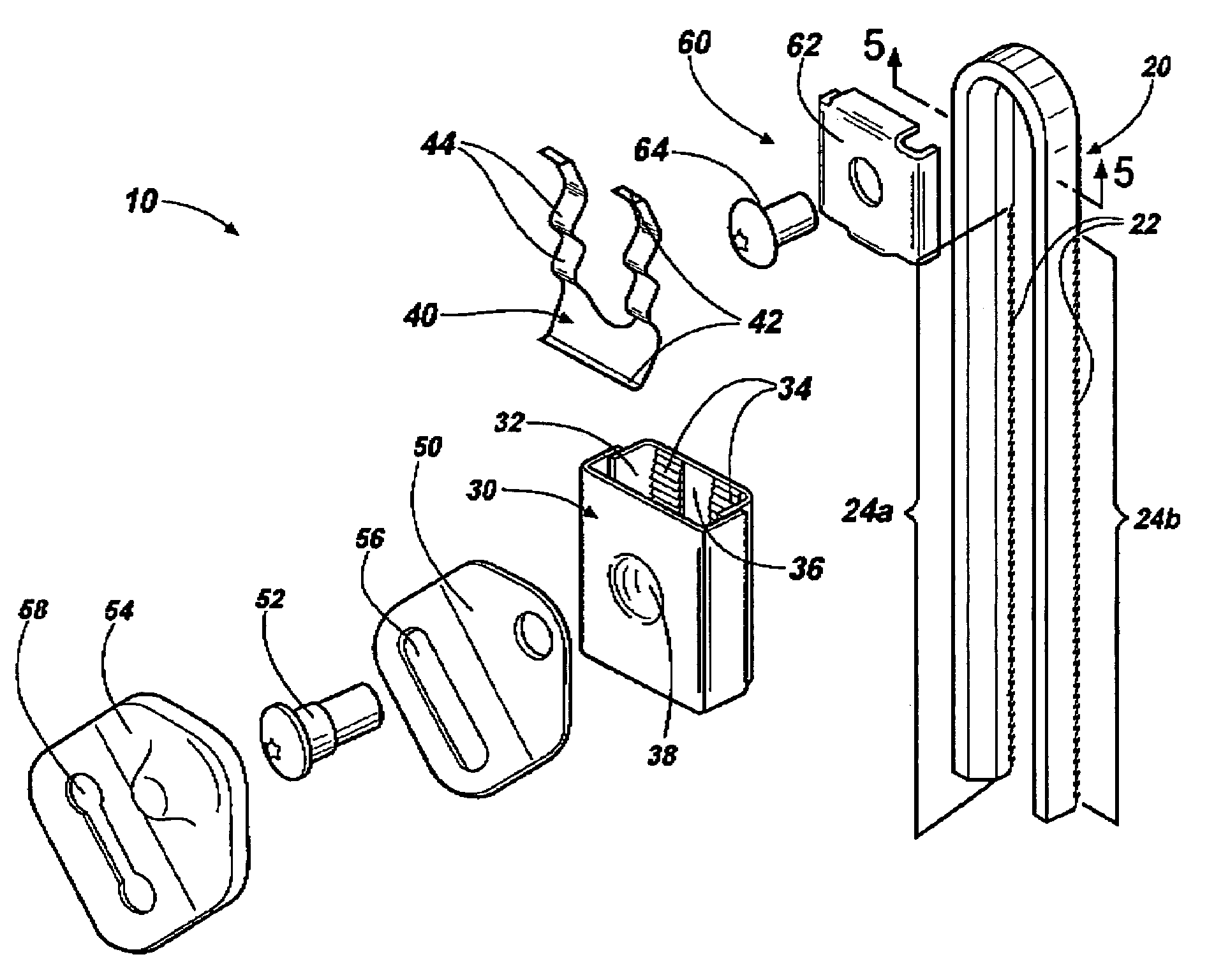
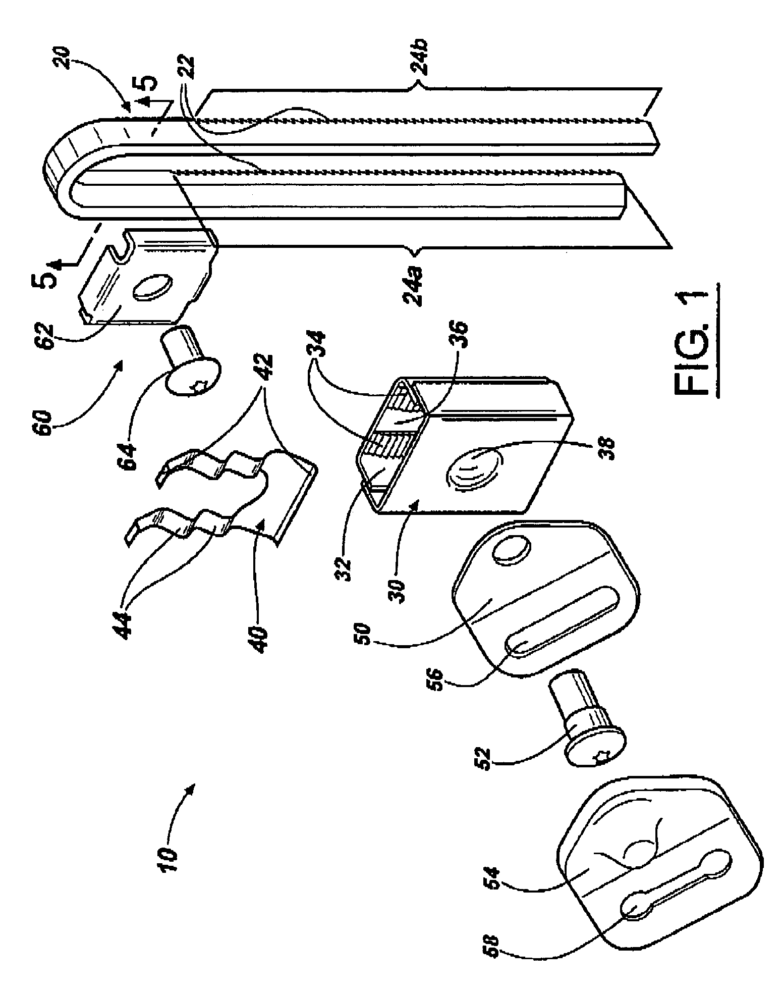
[0017]Referring to the drawings, wherein like reference numerals refer to like elements, FIG. 1 an exploded view of a shoulder belt height adjuster assembly in accordance with the present invention, shown generally by numeral 10, for a motor vehicle. Assembly 10 includes a guide rail 20, a slide 30, and a biasing member 40. Guide rail 20 includes a plurality of fixed rail teeth 22 disposed along at least one, in this case two, longitudinal portions 24a, 24b. The slide 30 includes an aperture 32 formed therein for slidably receiving the guide rail 20 along the longitudinal portions 24a, 24b. Slide 30 further includes a plurality of fixed slide teeth 34 disposed on an interior slide surface 36. In the present description, the term “fixed” is meant to describe gear-like teeth structures that are not moveable relative to an underlying surface. For example, the fixed slide teeth 34 are not moveable (e.g. rotatable, slidable, etc.) relative to the interior slide surface 36.

[0018]As shown ...


PUM


Abstract

The invention provides a shoulder belt height adjuster assembly and a method of adjusting the same. The assembly includes a guide rail, a slide, and a biasing member. The guide rail includes a plurality of fixed rail teeth disposed along at least one longitudinal portion. The slide includes an aperture formed therein for slidably receiving the guide rail along the longitudinal portion. The slide further includes a plurality of fixed slide teeth disposed on an interior slide surface. The biasing member is operably attached to the slide aperture for selectively engaging at least one of the fixed slide teeth into at least one of the fixed rail teeth. The engagement prevents slidable movement of the slide relative to the guide rail in a downward direction. The method includes selectively preventing sliding movement of a slide relative to a guide rail, sliding the slide in an upward direction by applying an upward force, and sliding the slide in a downward direction by applying a pressing force and a downward force.

Description

TECHNICAL FIELD OF THE INVENTION[0001]The present invention relates generally to vehicular restraint systems. More particularly, the invention relates to a shoulder belt height adjuster assembly and method of operating the same.BACKGROUND OF THE INVENTION[0002]Motor vehicles typically include active restraint systems such as over-the-shoulder safety belts. Such belts are generally attached to a vehicle door pillar at a position slightly above a passenger shoulder. As a passenger's height may vary considerably, it is sometimes desirable to provide a strategy for adjusting the vertical pillar position of the shoulder belt relative to the passenger. Adjustment of the shoulder belt height at the pillar position may offer optimal safety belt operation and ergonomics.[0003]Several strategies developed to provide shoulder belt height adjustment involve the use of a slidable member that moves vertically relative to a guide rail mounted to the vehicle pillar. Examples of such strategies incl...

Claims


Application Information

Patent Timeline
Patent Type & Authority Patents(United States)
IPC IPC(8): B60R22/20B60R22/24
CPCB60R22/24B60R22/202
Inventor HOFFMANN, ARTHURDROBOT, THOMASDLUGOSZ, ARTURHELNER, JEFFREY
Owner FCA US
Why Eureka
Try Eureka