Optical devices particularly for remote viewing applications

a technology for remote viewing and optical devices, applied in the field of optical devices, can solve the problems of limited performance, heavy hud systems, and many significant drawbacks of the current hud system, and achieve the effects of convenient structure and fabrication, compact and simple modules, and high fov

Active Publication Date: 2006-04-04
LUMUS LTD
View PDF6 Cites 210 Cited by
  • Summary
  • Abstract
  • Description
  • Claims
  • Application Information

AI Technical Summary

Benefits of technology

[0004]The present invention facilitates the structure and fabrication of very simple and high-performance optical modules for, amongst other applications, periscopes. The invention allows systems to achieve a relatively high FOV while maintaining a compact and simple module. The optical system offered by the present invention is particularly advantageous because it can be readily incorporated even into optical systems having specialized configurations.
[0006]An important application of the present invention relates to its implementation in a compact HUD, which alleviates the aforementioned drawbacks. In the HUD design of the current invention, the total volume of the system is significantly reduced while retaining the achievable IFOV. Hence, the overall system is very compact and can readily be installed in a variety of configurations for a wide range of applications.
[0007]A further application of the present invention provides a compact display with a wide FOV for HMDs, whereby an optical module serves both as an imaging lens and a combiner and a two-dimensional display is imaged to infinity and reflected into the eye of an observer. The display can be obtained directly, either from a cathode ray tube (CRT) or a liquid crystal display (LCD), or indirectly, by means of a relay lens or an optical fiber bundle. Typically, the display is comprised of an array of points, imaged to infinity by a collimating lens and transmitted into the eye of a viewer by means of a partially reflecting surface acting as a combiner. Usually, a conventional, free-space optical module is used for these purposes. Unfortunately, as the desired FOV of the system is increased, however, the optical module becomes heavier, bulkier and very complicated to use. This is a major drawback in head-mounted applications wherein the system should be as light and compact as possible.
[0009]The present invention facilitates the structure and fabrication of very compact HMDs. The invention allows relatively wide FOVs together with relatively large eye-motion-box values. The resulting optical system offers a large, high-quality image, which also accommodates large movements of the eye.
[0010]For all of the possible applications, the present invention is particularly advantageous for substrate-mode configurations, i.e., for a configuration comprising a light-transmitting substrate having at least two major surfaces and edges, optical means for coupling light from the imaging module into the substrate by total internal reflection, and at least one partially reflecting surface located in the substrate for coupling the light onto the viewer's eye. The combination of the present invention with a substrate-mode configuration can yield a very compact and convenient optical system along with a large IFOV and large eye-motion-box.
[0011]A broad object of the present invention, therefore, is to alleviate the drawbacks of state-of-the-art optical devices and, in particular, remote viewing display devices, and to provide optical devices and systems with improved performance.

Problems solved by technology

State-of-the-art HUDs, nevertheless, suffer from several significant drawbacks.
As a result, the present HUD systems are either bulky and large, requiring considerable installation space which is inconvenient, and at times, even unsafe, or suffer from limited performance.
Unfortunately, as the desired FOV of the system is increased, however, the optical module becomes heavier, bulkier and very complicated to use.
This is a major drawback in head-mounted applications wherein the system should be as light and compact as possible.

Method used


Image

  • Optical devices particularly for remote viewing applications
  • Optical devices particularly for remote viewing applications
  • Optical devices particularly for remote viewing applications

Examples


Embodiment Construction

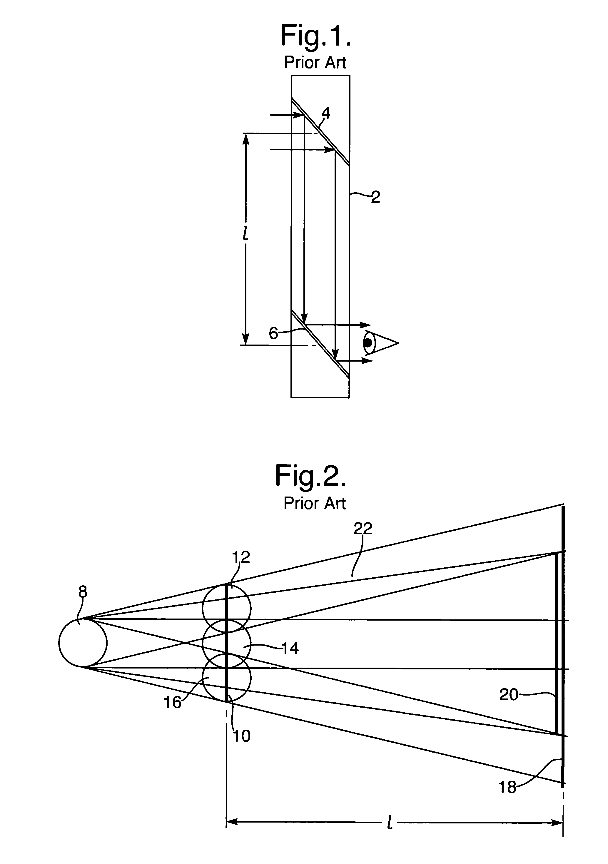
[0022]Remote viewing optical systems, and periscopes in particular, are optical systems designed to displace the object space reference point away from the eye space reference point. This allows the observer to look over or around an intervening obstacle, or to view objects in a dangerous location or environment while the observer is in a safer location or environment. A submarine periscope is the typical example, but many other applications, both military and non-military, are envisioned.

[0023]FIG. 1 illustrates the simplest form of a prior art periscope 2, having a pair of optical elements 4 and 6, e.g., a pair of folding mirrors, which are used to allow a viewer to see over a nearby obstacle. The basic geometry of this embodiment imposes limitations on the performance of the system. This is especially true for systems with a very wide FOV and a constraint on the distance, l, between the folding-in optical element 4 and the folding-out element 6.

[0024]FIG. 2 illustrates an unfolde...


PUM


Abstract

There is provided an optical device for transferring light within a given field-of-view, comprising an input aperture; reflecting surfaces, and an output aperture located in spaced-apart relationship from the input aperture such that light waves, located within the field-of-view, that enter the optical device through the input aperture, exit the optical device through the output aperture, wherein the reflecting surfaces are at least one pair of parallel reflecting surfaces and that part of the light waves located within the field-of-view that enter the input aperture, pass directly to the output aperture without being reflected off the at least one pair of parallel reflecting surfaces, while another part of the light waves within the field-of-view that enters the input aperture, arrives at the output aperture after being twice reflected by the at least one pair of parallel reflecting surfaces.

Description

FIELD OF THE INVENTION[0001]The present invention relates to optical devices, and in particular to devices whereby an object is viewed remotely, with a large field-of-view (FOV) and in which the system aperture is limited by various constrains.[0002]The invention can advantageously be implemented in a large number of imaging applications, such as periscopes, as well as head-mounted and head-up displays.BACKGROUND OF THE INVENTION[0003]There are many applications in which remote viewing is necessary, as the object to be viewed is located in an environment hostile to the viewer, or it is inaccessible to the viewer without causing unacceptable damage to its environment. Periscopes for military applications fall into the former category, while endoscopes, colonoscopes, laryngoscopes and otoscopes, for medical applications, fall into the latter. An additional category is that of see-through imaging systems, such us head-mounted displays (HMDs) and head-up displays (HUDs), wherein the opt...

Claims


Application Information

Patent Timeline
Patent Type & Authority Patents(United States)
IPC IPC(8): G02B5/08G02B5/18G02B6/00G02B27/00G02B27/01
CPCG02B27/0101G02B27/0172G02B27/0081G02B5/18G02B6/00G02B2027/0125
Inventor AMITAI, YAAKOV
Owner LUMUS LTD
Why Eureka
Try Eureka