Wire cover with two longitudinal halves connectable around electric wires

a technology of connecting wires and covers, which is applied in the direction of coupling bases/cases, coupling device connections, electrical appliances, etc., can solve the problems of damage to the insulation coating of electric wires, and achieve the effect of reducing the outer dimension of the cover, simplifying the construction of the connector, and facilitating the connection

Inactive Publication Date: 2006-04-04
SUMITOMO WIRING SYST LTD
View PDF8 Cites 36 Cited by
  • Summary
  • Abstract
  • Description
  • Claims
  • Application Information

AI Technical Summary

Benefits of technology

[0016]The engaging projections are slightly rearward from the edge of the butting wall along the connecting direction. Thus, a portion of an outer surface of the butting wall between the edge of the butting wall and the engaging projection defines a temporary holding surface that supports the locking piece before the locking piece reaches the engaging projection during the connection of the halves. Consequently, the halves are held in a normal posture. The temporary holding surface of the butting wall stabilizes the posture of each of the halves in an initial stage of the connecting operation and before the locking piece rides over the engaging projection. Thus, unlike the prior art, it is possible to prevent the halves from being connected in an inclined posture and the connection can be accomplished smoothly.
[0017]A guide preferably is formed on the butting wall for guiding the locking piece in the direction in which the halves are connected. The guide prevents the locking piece from deviating in the front-to-back direction on the upper surface of the butting wall. Accordingly, the halves will not be connected in an inclined posture and the connection can be accomplished smoothly.
[0018]An accommodation concavity preferably is formed on an outer surface of the butting wall and opens toward the edge of the butting wall. The locking projection is formed in the accommodation concavity. The locking piece is formed on a level that allows the locking piece to slide on an inner surface of the accommodation concavity while the halves are being connected together. Additionally, the locking piece can fit in the accommodation concavity after the two halves are connected. Thus, the locking piece and the accommodation concavity overlap in a thickness direction of the butting wall. Therefore, the outer dimension of the cover is reduced.
[0019]The guide preferably is integral with the accommodation concavity. Thus, the guide cooperates with the inner sidewall of the accommodation concavity, and the construction of the connector is simplified.
[0020]The cover may include a lock on an inner peripheral surface of an end of the cover at a side from which electric wires extend. The lock preferably engages a periphery of the corrugate tube to allow the corrugate tube to be mounted unremovably on the cover. An electric wire guide preferably is adjacent the lock and defines a diameter of a path for the electric wires extended from the corrugate tube that is smaller than an inner diameter of an edge of the corrugate tube. Thus, the electric wires do not have a sliding contact with the edge of the corrugate tube even if the wires are shaken, and the insulating coating of the wires cannot be damaged.
[0021]The electric wire guide preferably includes half annular projections formed circumferentially on an inner surface of each half of the cover. Thus, an end of the corrugate tube is inserted into one of the half covers. The electric wires then are positioned on the inner periphery of the half projection, and the half covers are fixed together by a locking mechanism. Accordingly, the corrugate tube and the electric wires can be mounted easily. The path for the electric wires is regulated by the inner periphery of the annular projection, and the electric wires will not be cut by the periphery of the cover.

Problems solved by technology

As a result, there is a possibility that insulating coatings of the electric wires W will be damaged.

Method used


Image

  • Wire cover with two longitudinal halves connectable around electric wires
  • Wire cover with two longitudinal halves connectable around electric wires
  • Wire cover with two longitudinal halves connectable around electric wires

Examples


Embodiment Construction

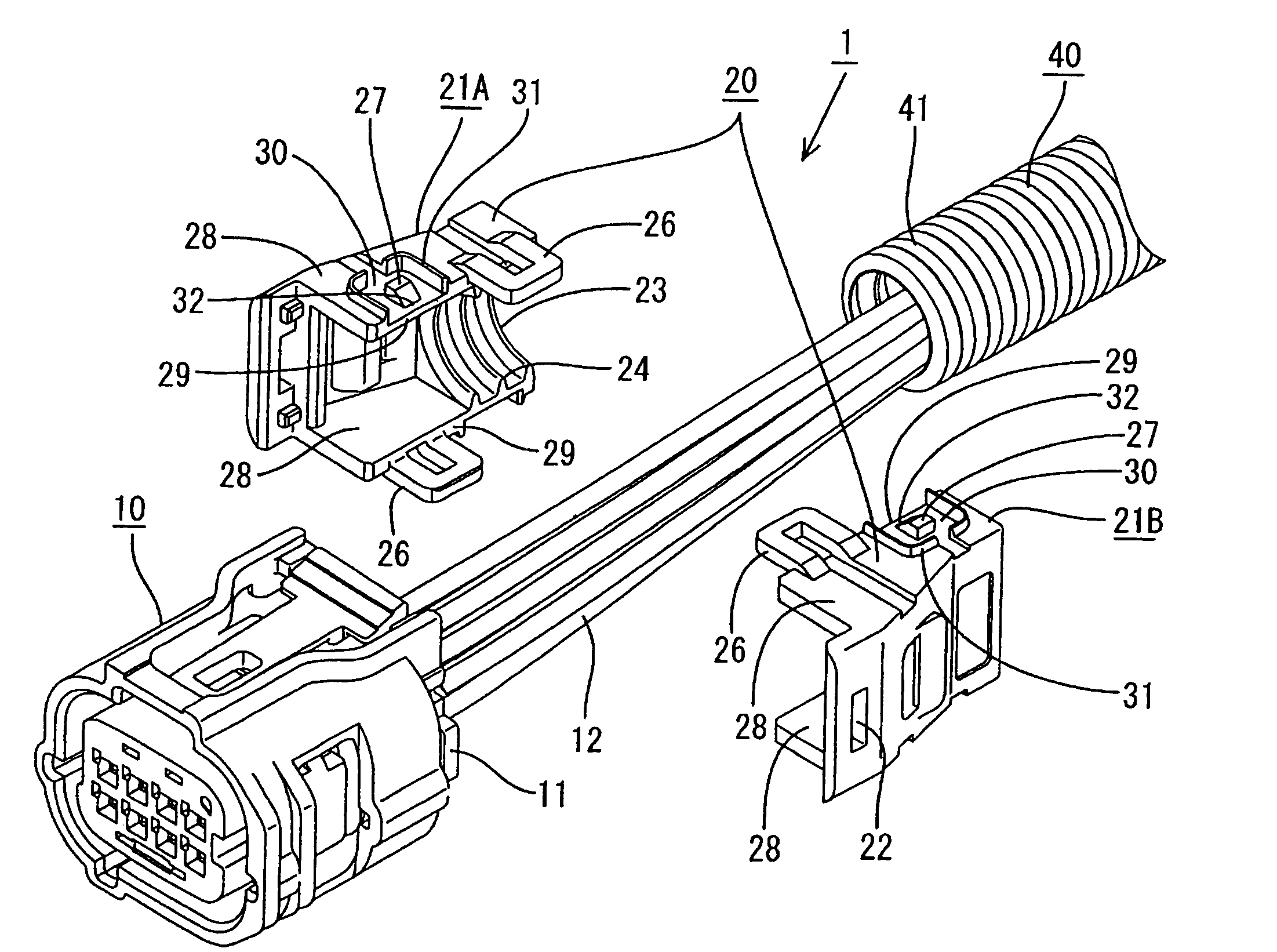
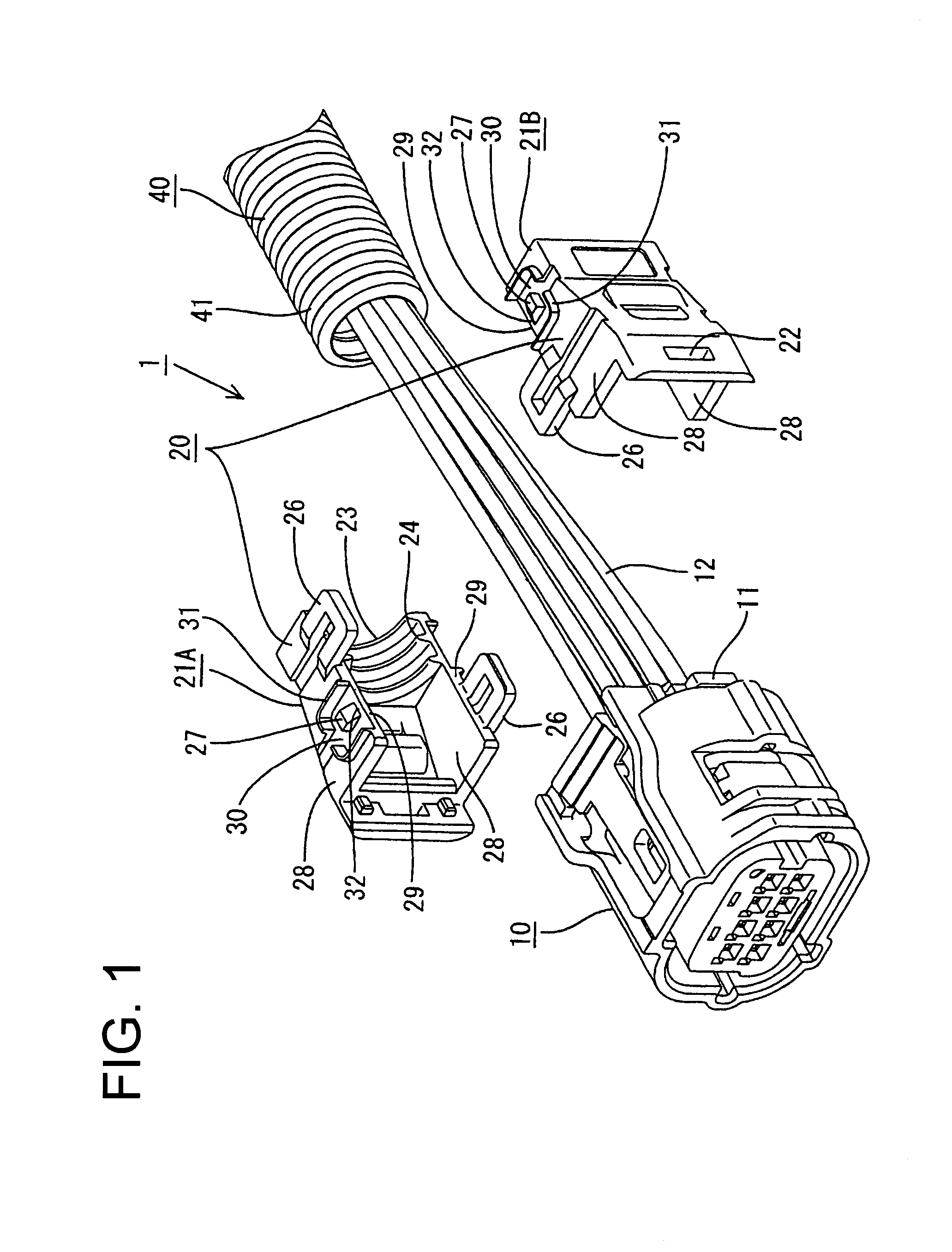
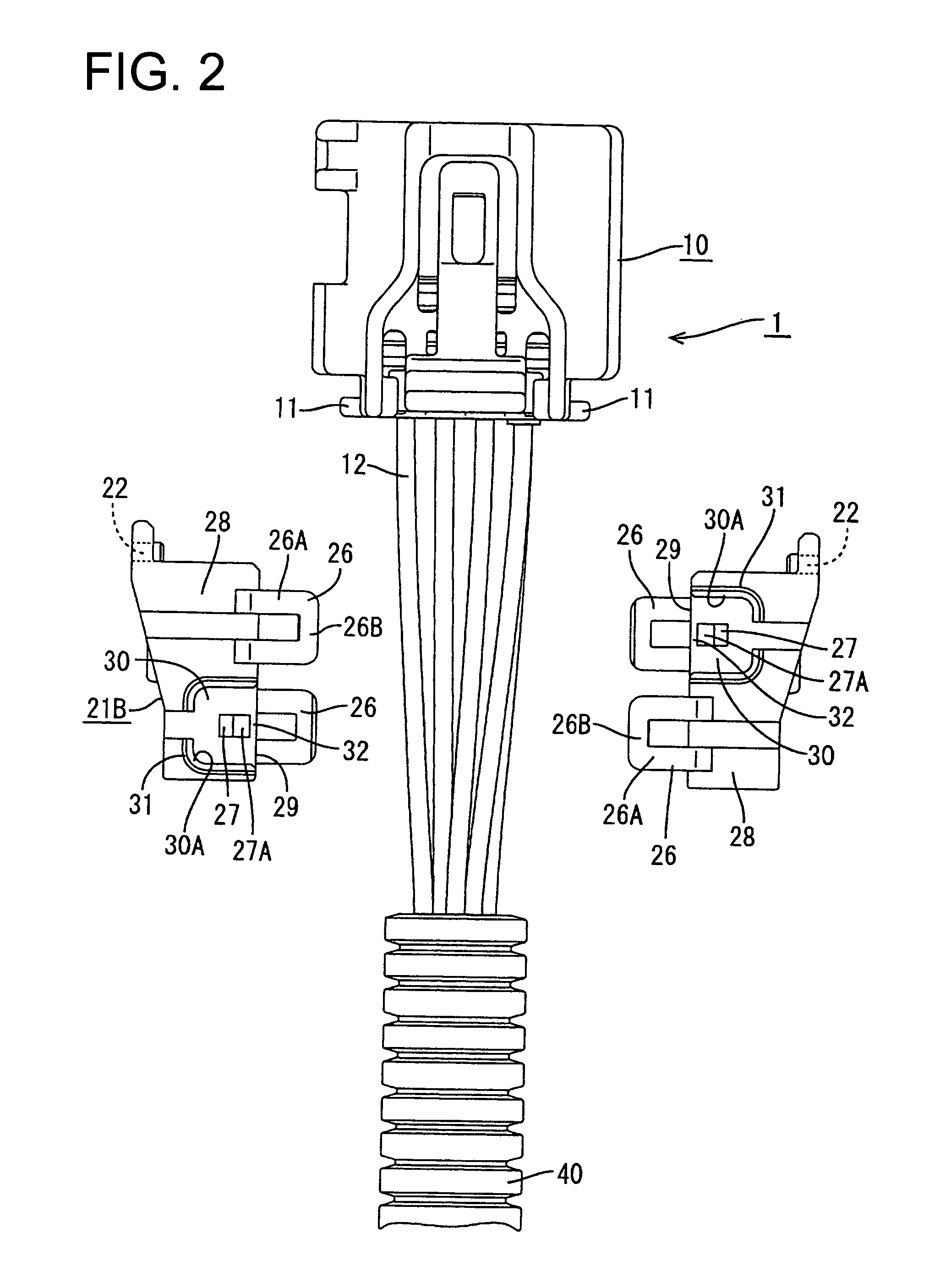
[0041]A connector according to the invention is identified generally by the numeral 1 in FIGS. 1 through 9. The connector 1 includes a housing 10 that accommodates terminal fittings (not shown) connected to electric wires 12 and a cover 20. The cover 20 is constituted of two halves 21A and 21B and is mounted on the housing 10 (see FIGS. 1 through 3). In the following description, the direction in which the electric wires 12 are extended from the connector housing 10 is defined as the front-to-back direction. The direction in which the halves 21A and 21B are connected to each other is defined as the right-to-left direction. The direction crossing the above two directions (i.e. the direction crossing the paper on which FIG. 2 is shown) is defined as the vertical direction.

[0042]The wires 12 connected to the terminal fittings extend from a rear end of the housing 10. Mounting projections 11 for mounting the cover 20 on the connector housing 10 are formed at right and left sides of a re...


PUM


Abstract

A cover (20) has opposed halves (21) with butting walls (28). An engaging projection (27) is formed in an accommodation concavity (30) rearward from an edge (29) of the butting wall (28). A portion between the engaging projection (27) and the edge (29A) on a bottom surface of the accommodation concavity (30) defines a temporary holding surface (32) which is contacted by a connection portion (26B) of a locking arm (26) on the opposed half (21). The temporary holding surface (32) stabilizes the posture of each half (21) before the locking arm (26) rides over the engaging projection (27). Thus, halves (21) do not incline and the connection operation is accomplished smoothly.

Description

BACKGROUND OF THE INVENTION[0001]1. Field of the Invention[0002]The invention relates to a connector with a cover to protect electric wires extended from a connector housing.[0003]2. Description of the Related Art[0004]Japanese Patent Application Laid-Open No. 10-27645 and FIGS. 16–18 herein disclose a connector with a cover for protecting electric wires that extend from a connector housing. The cover is formed as two longitudinal halves of a rectangular tube.[0005]An engaging portion and a receiving portion are formed on each of the upper and lower butting walls that are butted against each other when the halves of the cover are connected. The engaging portions on opposed edges are disposed obliquely, and the receiving portions on the opposed edges also are disposed obliquely. The line that connects the engaging portions to each other crosses the line that connects the receiving portions to each other. Additionally the engaging portions of one half align with the receiving portions...

Claims


Application Information

Patent Timeline
Patent Type & Authority Patents(United States)
IPC IPC(8): H01R13/58H01R13/50H01R13/506H01R13/56
CPCH01R13/562H01R13/501H01R13/567H01R13/506
Inventor TSUJI, TAKESHIICHIO, TOSHIFUMIOKAMOTO, MICHIAKI
Owner SUMITOMO WIRING SYST LTD
Why Eureka
Try Eureka