Position sensing cylinder cap for ease of service and assembly

a technology of position sensing cylinder and cylinder body, which is applied in the field of fluid cylinder, can solve the problems of inability to easily service, inconvenient access to position sensors or sensor electronics when service is required, and inability to position sensors or sensor electronics outside the cylinder body

Inactive Publication Date: 2006-04-04
CATERPILLAR INC
View PDF39 Cites 52 Cited by
  • Summary
  • Abstract
  • Description
  • Claims
  • Application Information

AI Technical Summary

Benefits of technology

[0012]The present invention further provides a method of operating a fluid cylinder including a piston assembly slideably disposed in a body and a piston position sensor assembly adapted to be encased within and removably receivable within the fluid cylinder, the method comprising: moving the piston assembly along an axial reference within the body; sensing a piston position within a sensor portion of the piston position sensor assembly through communication between a sensor portion and an interactive element attached to the piston assembly; telescopically receiving the sensor portion within the piston assembly; transmitting the sensed piston position to an encased sensor electronics module which is piloted along the reference axis within a pilot portion of a housing assembly attached to the body; and providing substantially no leakage of working fluid between a piston chamber and an area external thereto through a sealed engagement between the housing assembly and the sensor assembly.

Problems solved by technology

However, known systems such as these have been found to provide only a partial solution to the problems encountered as electronic components required for the operation of the sensors and transducers thereof remain externally located, and as a result sensor inaccuracies and even worse sensor failure is likely due to the cylinder and sensor being subjected to adverse operating and environmental factors.
However, the end caps are generally welded to the body making the cylinder a unitary element and one which is often not readily serviceable without removing the cylinder from the machine or linkage to which it is attached.
In view that many cylinder applications require robust usage which include suitable operation even if the cylinder is prone to impact and abrasion from rock, earth, slag, debris, etc. during use, in combination with the requirement that the cylinders include the ability to transfer significant force loads therethrough, it may be unacceptable to position the sensor or sensor electronics outside of the cylinder body even if an impact shield is positioned thereover.
Moreover, if it is attempted to at least partially conceal the sensor and / or sensor electronics within a sturdy outer structure, then it is often difficult to easily access the position sensor or sensor electronics when service is required.
Unfortunately, if a position sensor needs to be serviced or replaced, it is often necessary to replace the entire cylinder unit at a significant expense to the machine owner or operator.

Method used


Image

  • Position sensing cylinder cap for ease of service and assembly
  • Position sensing cylinder cap for ease of service and assembly
  • Position sensing cylinder cap for ease of service and assembly

Examples


first embodiment

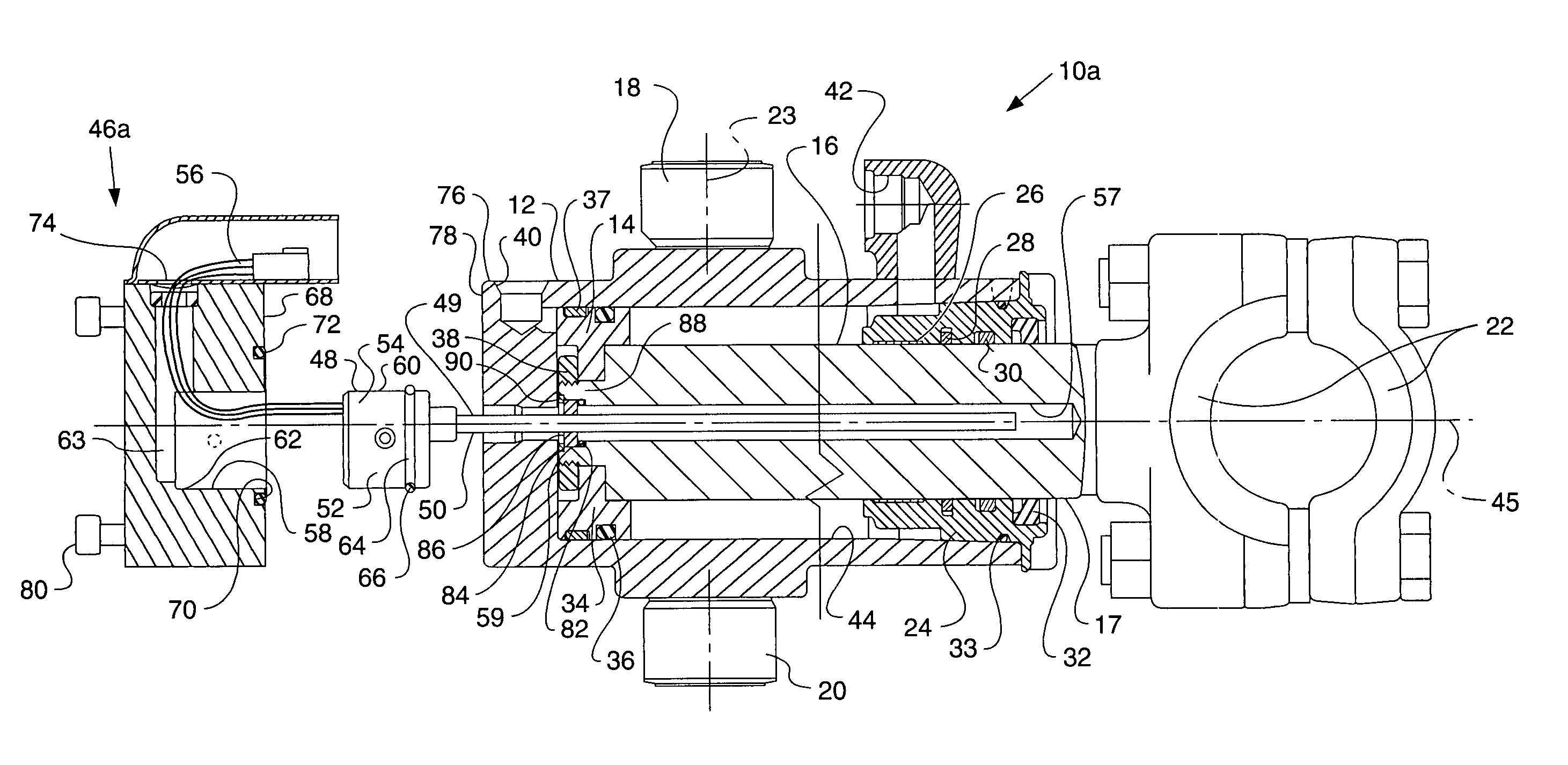
[0026]Referring to FIG. 1, a fluid actuator arrangement 10a according to the present invention is shown and includes a body 12 and a piston assembly 14 connected with a rod assembly 16. Although the actuator assembly 10a may be depicted as a trunnion mount actuator it is envisioned that the present invention is equally applicable to other types of actuators such as clevis mount actuators or any other actuator known to those having ordinary skill in the actuator arts. Rod assembly 16 includes a rod 17 which is slideably disposed within the body 12 of the actuator.

[0027]The actuator assembly 10a may include a pair of mounting bosses 18, 20, or a trunnion, projecting radially, outwardly from the body 12, and the rod 17 may be attached to an eye or rod mount 22. In operation, for example, the mounting bosses 18, 20 may be retained in a receiving mount (not shown), such as a pillow block or a yoke, such that the cylinder would be rotatable about a transverse reference axis 23. The rod mo...

second embodiment

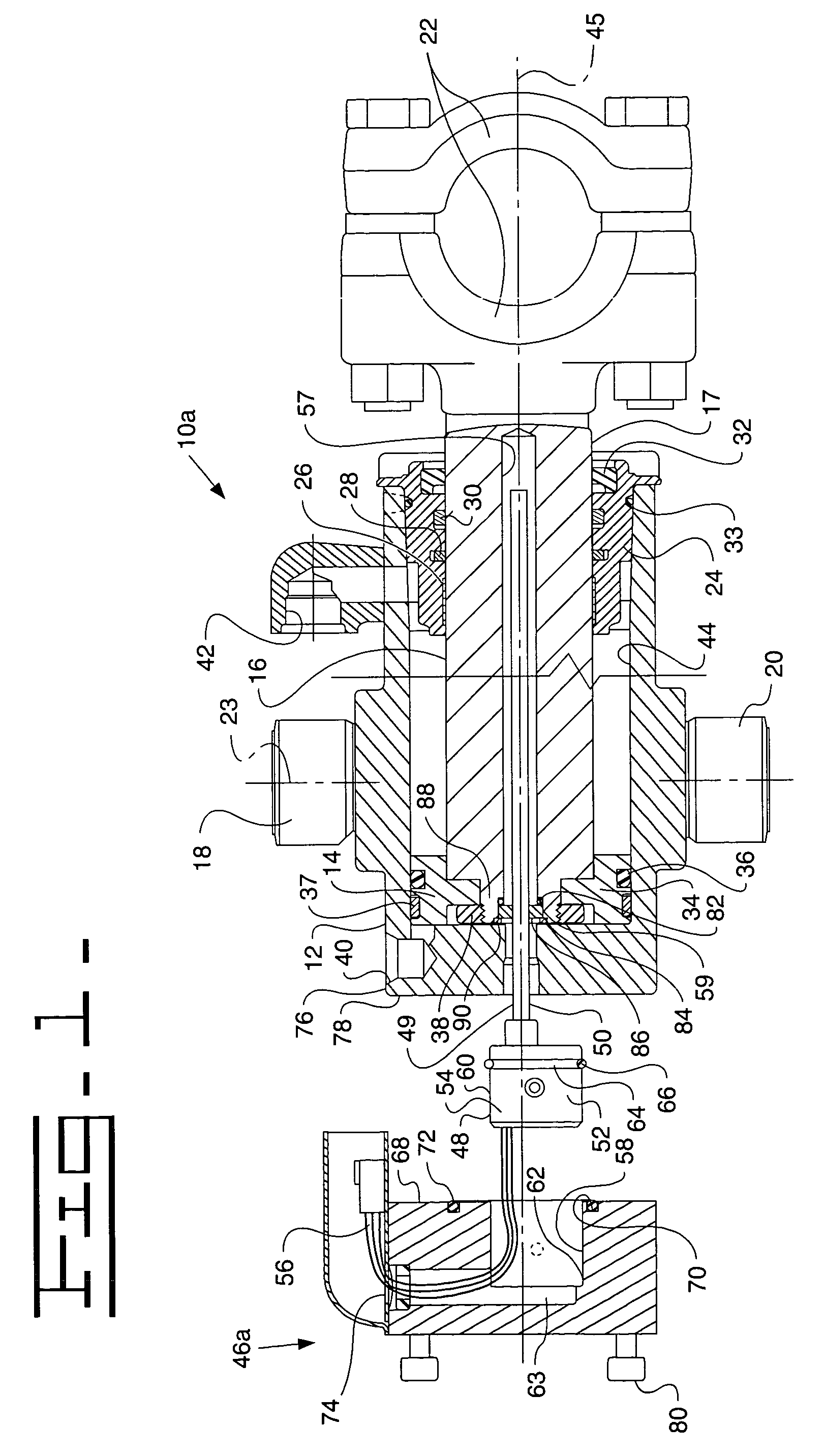
[0036]Referring to FIG. 2, a fluid actuator 10b is shown and includes a stepped portion 96 of the housing assembly 46b attached to an end 94 of the body 12. The body 12 and the housing assembly 46b may be integrally attached, for example by a welded joint 98 or other known sealed attachment means which may be customarily used. A second end 100 of the housing assembly 46b includes a groove 102 to accommodate an O-ring 104 disposed therein. The housing assembly 46b further includes a cover 106 in sealed abutment with the end 100 through the O-ring 104. A plurality of fasteners 108 is provided to attach the cover 106 to the end 100 of the housing 46b. A spacer 110 is provided within the pilot opening 58 to ensure that there is insignificant movement of the sensor body 52 in the axial direction. The spacer 110 may be, for example, a C-shaped spacer that is arranged to allow wires 56 to pass therethrough. Further, a set screw (not shown) may be threaded radially through the housing 46b a...

third embodiment

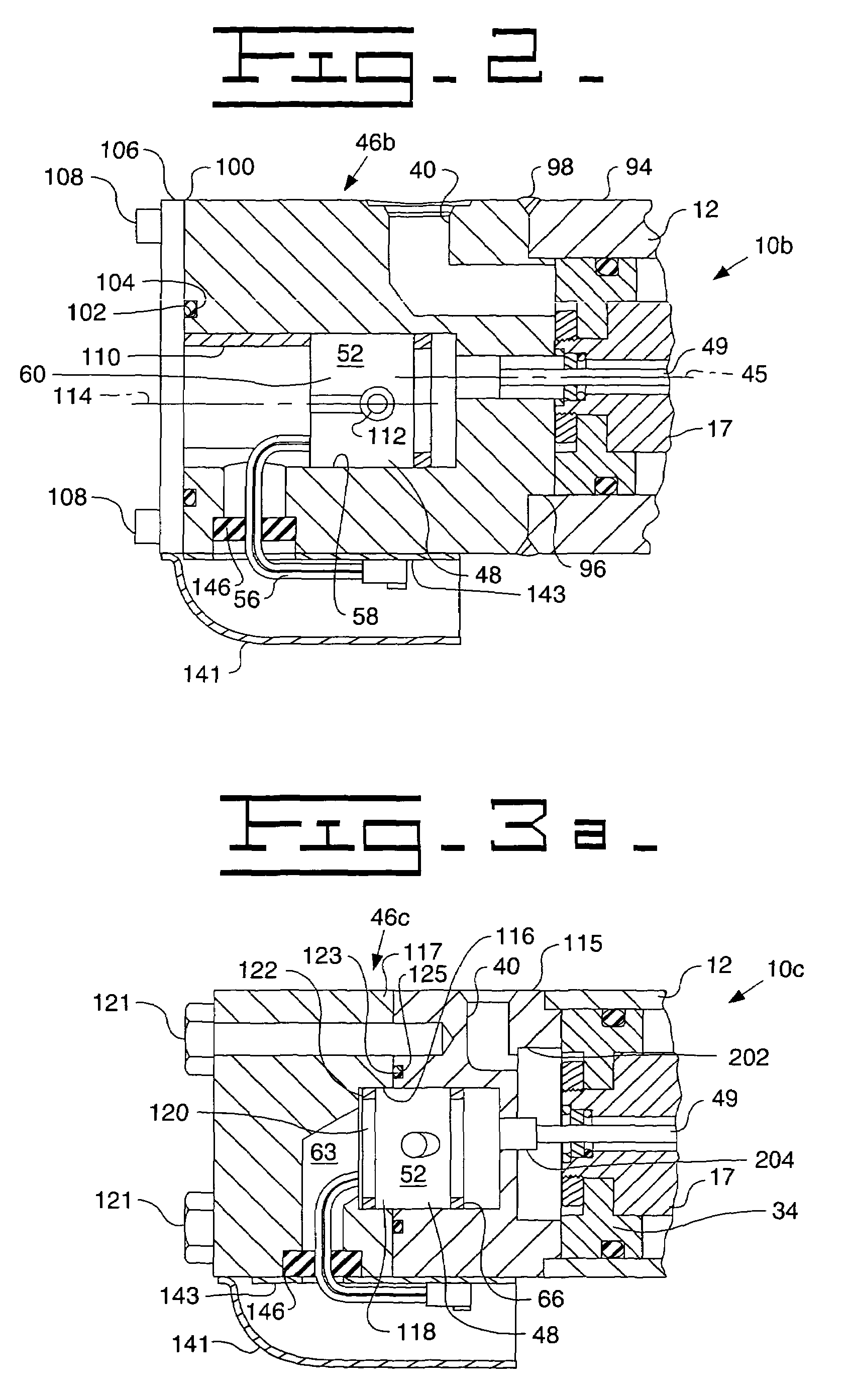
[0037]Referring to FIG. 3A, a fluid actuator 10c is shown and includes a two-part housing 46c including a first housing portion 115 and a second housing portion 117. The second portion 117 of the housing 46c includes a recessed opening 116 provided therein. It will be understood that when it is desired to service or remove the sensor assembly 48, the second portion 117 may be removed to expose an extended end portion 118 of the sensor body 52. In so doing, the sensor 48 may be easier to be removed. The actuator assembly 10c may also include a back-up seal 122, which may be provided in a groove 120 within the end 118 of the sensor body 52. If, for example, the seal assembly 66 were to fail then the back-up seal 122 would prevent fluid from entering the dead space 63 and ultimately leaking from the actuator assembly. The first and second housing portions 115, 117, which may be attached by one or more fasteners 121, such as threaded fasteners, may be sealed through an O-ring 123. The O...


PUM


Abstract

An actuator arrangement includes a body and at least one of a piston assembly and a rod assembly slideably disposed in the body. A sensor arrangement includes a sensor, a sensor electronics module, and an interactive element. The interactive element is moveable relative to the sensor, wherein a position of the interactive element indicative of a position of the at least one of a piston assembly and a rod assembly is communicated to the sensor electronics module through the sensor. A housing assembly is attached to an end of the body and includes a sensor pilot portion. The sensor pilot portion in the housing assembly is structured and arranged to sealably receive the sensor electronics module therein, wherein the sensor electronics module is encased within the housing.

Description

[0001]This application claims the benefit of U.S. Provisional Application No. 60 / 437,521, filed Dec. 31, 2002, which is hereby incorporated by reference in its entirety.TECHNICAL FIELD[0002]This invention relates generally to a fluid cylinder, such as a hydraulic or a pneumatic cylinder or the like, and more particularly to a fluid cylinder including an embedded sensor and sensor electronics module for determining positional information for a rod of the cylinder.BACKGROUND ART[0003]Known linkage systems utilizing fluid cylinders for changing link length and angular orientation typically utilize controls wherein information relating to the length and / or velocity of movement of one or more cylinder rods is required. The electrical aspects of control apparatus for such systems typically require the use of a variety of sensors, including, but not limited to, lever position sensors and linkage position sensors, and also utilize electro-hydraulic valves and an onboard electronic control m...

Claims


Application Information

Patent Timeline
Patent Type & Authority Patents(United States)
IPC IPC(8): G01B7/14F15B15/28
CPCF15B15/2892F15B15/2815
Inventor BLUBAUGH, JAMES F.HAMASAGAR, ARUN M.MCINTYRE, DAVID J.SKINNER, THOMAS G.WILTZ, SEAN P.
Owner CATERPILLAR INC
Why Eureka
Try Eureka