Sensor for ignition timing device

a timing device and sensor technology, applied in the direction of electric ignition installation, mechanical equipment, machines/engines, etc., can solve the problems of oil mist emerging from the timing port, particularly troublesome timing of internal combustion engines, and difficulty of harley-davidsonTM engines

Inactive Publication Date: 2006-04-04
THOMSEN JEFFREY E
View PDF32 Cites 0 Cited by
  • Summary
  • Abstract
  • Description
  • Claims
  • Application Information

AI Technical Summary

Problems solved by technology

Some internal combustion engines are particularly troublesome to time.
A Harley-Davidson™ engine is known for its difficulty.
Unfortunately, removal of the timing plug and operation of the engine causes an oil mist to emerge from the timing port.
The emerging oil makes the timing mark difficult to see as well as typically covers the mechanic and the surrounding area with oil.
However, the inside surface of the plug is substantially covered with oil, which obscures visibility of the timing mark.
Therefore, a mechanic operating by himself would find viewing the timing mark and adjusting the engine still to be difficult.

Method used


Image

  • Sensor for ignition timing device
  • Sensor for ignition timing device
  • Sensor for ignition timing device

Examples


Embodiment Construction

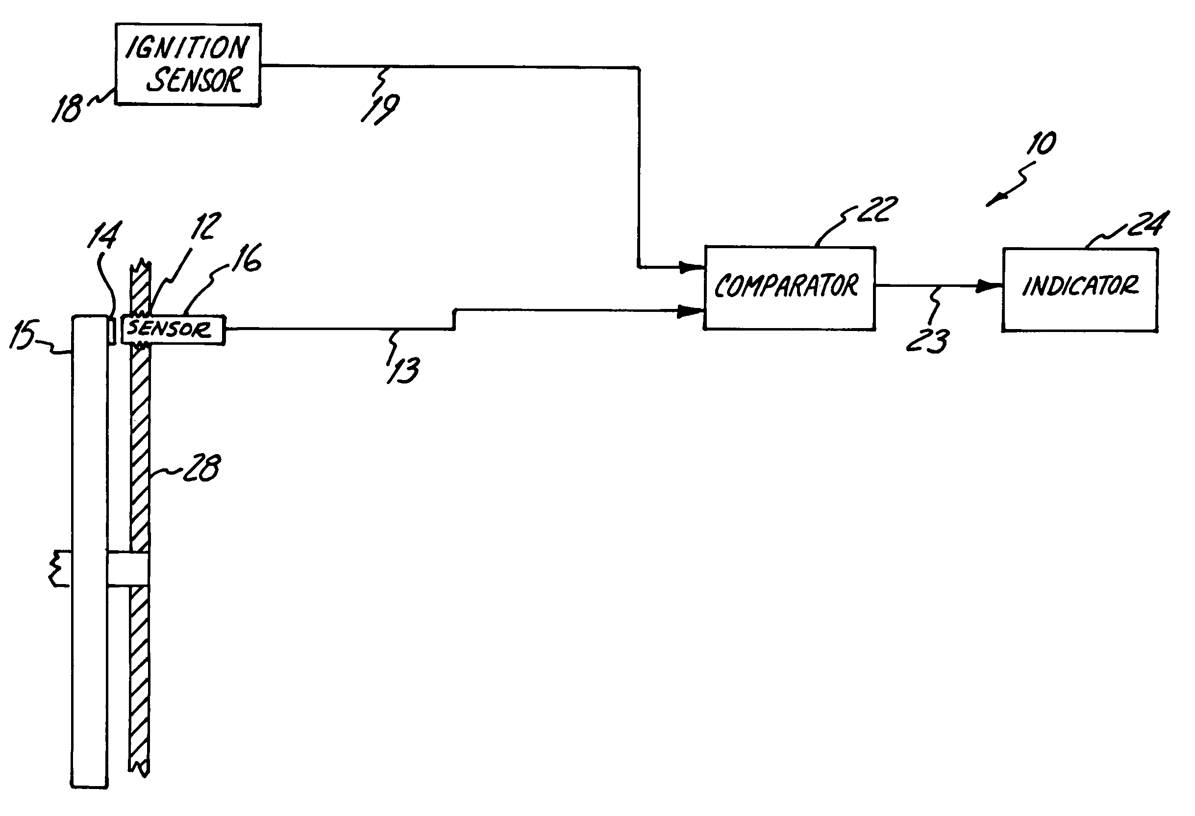
[0025]FIG. 1 schematically illustrates an ignition timing device 10 for timing an engine such as the Harley-Davidson™ motorcycle engine, which has a timing port 12 through which a timing mark 14 can be seen on a rotating member or flywheel 15. Although the timing mark 14 illustrated herein is a projection, it should be understood that the timing mark 14 is commonly a depression, for example, a machined slot or void in the flywheel 15. A sensor 16 secured proximate the timing port 12 provides a timing mark signal 13 indicative of periodic presence of the timing mark 14 as the engine is operated. An ignition sensor 18 is adapted to provide an ignition signal 19 indicative of the occurrence of the ignition spark. A comparator 22 (e.g. an “AND” gate) receives the timing mark signal 13 and the ignition signal 19. The comparator 22 provides an output signal 23 indicative of substantial simultaneous occurrence of the timing mark signal 13 and the ignition signal 19.

[0026]An indicator 24 re...


PUM


Abstract

A variable reluctance sensor for use with an ignition timing device includes a support tube insertable in a bore extending from a first end to a second end. A sensor housing is insertable in the bore, while a variable reluctance probe is disposed in the sensor housing.

Description

CROSS-REFERENCE TO RELATED APPLICATION[0001]This application is a divisional of and claims priority of U.S. patent application Ser. No. 10 / 191,680, now U.S. Pat. No. 6,664,789, filed Jul. 9, 2002, which is a continuation of and claims priority of U.S. patent application Ser. No. 09 / 412,097, now U.S. Pat. No. 6,429,658, filed Oct. 4, 1999, which claims benefit of U.S. Patent Application 60 / 103,026, filed Oct. 5, 1998, and 60 / 144,750, filed Jul. 21, 1999, all of which are herein incorporated by reference in their entirety.BACKGROUND OF THE INVENTION[0002]The present invention relates generally to an ignition timing device. More particularly, the present invention relates to an ignition timing device for use on Harley-Davidson™ engines.[0003]As is well known, the ignition spark used for detonation in an internal combustion engine must be timed to the position of a piston reciprocating within the combustion chamber. In order to time the engine, the manufacturer generally provides a timi...

Claims


Application Information

Patent Timeline
Patent Type & Authority Patents(United States)
IPC IPC(8): F02P17/00F02P5/00F02DF02D1/00G01P3/48
CPCF02P7/0675F02P17/06F02P7/073
Inventor THOMSEN, JEFFREY E.CLEMENTS, RICHARD L.
Owner THOMSEN JEFFREY E
Why Eureka
Try Eureka