Systems and methods for performing vibration analysis using a variable-reluctance sensor

a technology of resistance and vibration analysis, applied in the direction of magnetic property measurement, material magnetic variables, instruments, etc., can solve the problems of prone failure of accelerometers and relatively high cost, and achieve the effect of high reliability

Inactive Publication Date: 2012-01-12
HONEYWELL INT INC
View PDF3 Cites 0 Cited by
  • Summary
  • Abstract
  • Description
  • Claims
  • Application Information

AI Technical Summary

Benefits of technology

[0002]The present invention provides a balanced bridge variable-reluctance sensor with no internal circuit components or dielectric for performing vibration analysis in high-vibration, high-temperature, and other extreme environments. The present invention includes a variable-reluctance sensor in a vibration-sensing capacity. The present invention has inherently high reliability due to its simplicity. The sensor operates in environments as high as 300 degrees C. The sensor is solidly mounted to a structure that is being monitored and allows a vibration wave to pass through a floating sensor bridge. The sensor vibrates at the same frequency as the application being measured.

Problems solved by technology

These accelerometers are prone to failure and are relatively costly.
Silicon, solid-state, and accelerometer sensors require springs and dielectric compounds that are limited in their environmental installations.

Method used


Image

  • Systems and methods for performing vibration analysis using a variable-reluctance sensor
  • Systems and methods for performing vibration analysis using a variable-reluctance sensor
  • Systems and methods for performing vibration analysis using a variable-reluctance sensor

Examples


Embodiment Construction

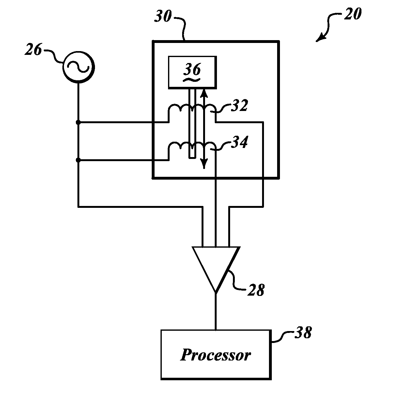
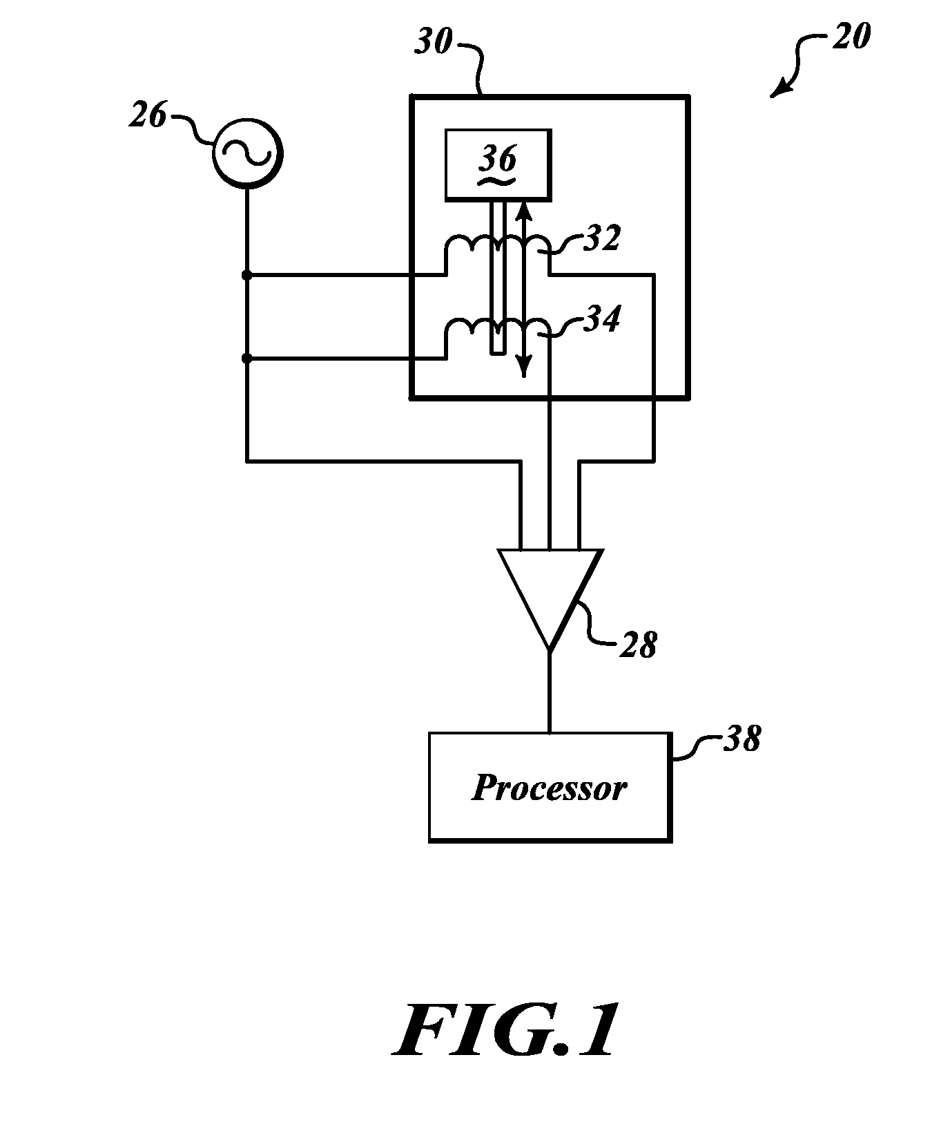
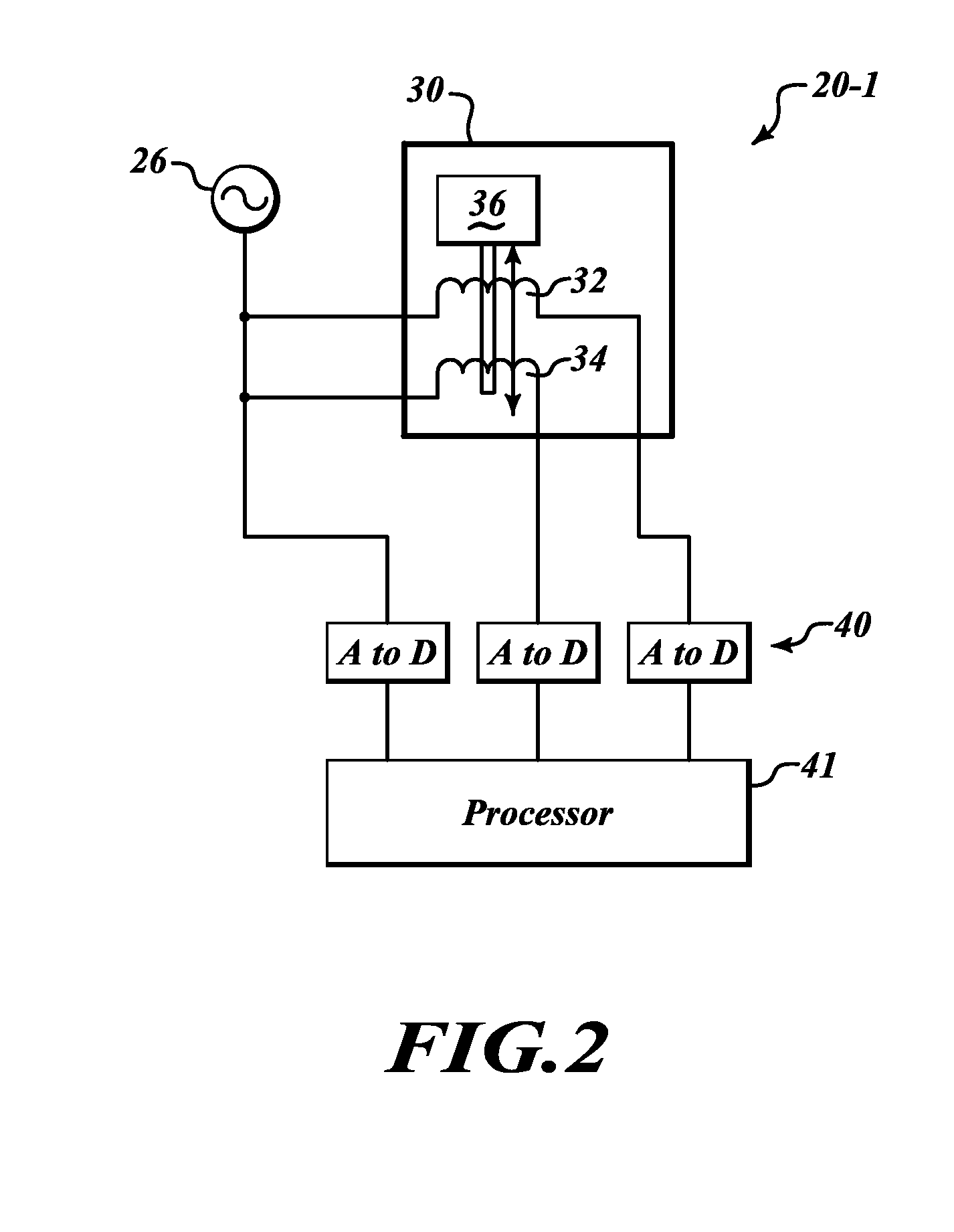
[0007]FIG. 1 illustrates an exemplary sensor circuit 20 that uses a variable-reluctance sensor 30 for sensing vibration of a structure to which the variable-reluctance sensor 30 is attached. The sensor circuit 20 also includes an oscillator 26, a comparator 28, and a processor 38.

[0008]The oscillator 26 is connected to a first coil 32 within the variable-reluctance sensor 30 and to an output end of a second coil 34 also located within the sensor 30 via a combiner (not shown). The input end of the first coil 32 is connected to a first input of the comparator 28. The output end of the second coil 34 is connected to a second input of the comparator 28. An output of the comparator 28 is attached to the processor 38.

[0009]The oscillator 26 sends a signal through the variable-reluctance sensor 30 via the input of the first coil 32. The signal produced by the oscillator 26 compared with the signal at the output of both the first coil 32 and the second coil 34 via the comparator 28. The var...


PUM


Abstract

A balanced bridge variable-reluctance sensor with no internal circuit components, springs, or dielectric for performing vibration analysis in high-vibration, high-temperature, and other extreme environments. The present invention includes a variable-reluctance sensor in a vibration-sensing capacity. The present invention has inherently high reliability due to its simplicity. The sensor is solidly mounted to a structure that is being monitored and allows a vibration wave to pass through a floating sensor bridge. The sensor vibrates at the same frequency as the application being measured.

Description

BACKGROUND OF THE INVENTION[0001]Current vibration sensor technology uses accelerometers that have a temperature-limited and sensitive dielectric or spring component. These accelerometers are prone to failure and are relatively costly. Silicon, solid-state, and accelerometer sensors require springs and dielectric compounds that are limited in their environmental installations.SUMMARY OF THE INVENTION[0002]The present invention provides a balanced bridge variable-reluctance sensor with no internal circuit components or dielectric for performing vibration analysis in high-vibration, high-temperature, and other extreme environments. The present invention includes a variable-reluctance sensor in a vibration-sensing capacity. The present invention has inherently high reliability due to its simplicity. The sensor operates in environments as high as 300 degrees C. The sensor is solidly mounted to a structure that is being monitored and allows a vibration wave to pass through a floating sen...

Claims


Application Information

Patent Timeline
Patent Type & Authority Applications(United States)
IPC IPC(8): G01B7/14G01P3/48
CPCG01H11/02
Inventor JACOBS, MIKE
Owner HONEYWELL INT INC
Why Eureka
Try Eureka