Torsional anomalies detection system

Active Publication Date: 2019-04-16
BELL HELICOPTER TEXTRON INC
View PDF41 Cites 0 Cited by
  • Summary
  • Abstract
  • Description
  • Claims
  • Application Information

AI Technical Summary

Problems solved by technology

However, accelerometers must be spread out along the length of the drive train as vibrations resulting from faulty parts are generally localized to the faulty part.

Method used


Image

  • Torsional anomalies detection system
  • Torsional anomalies detection system
  • Torsional anomalies detection system

Examples


Embodiment Construction

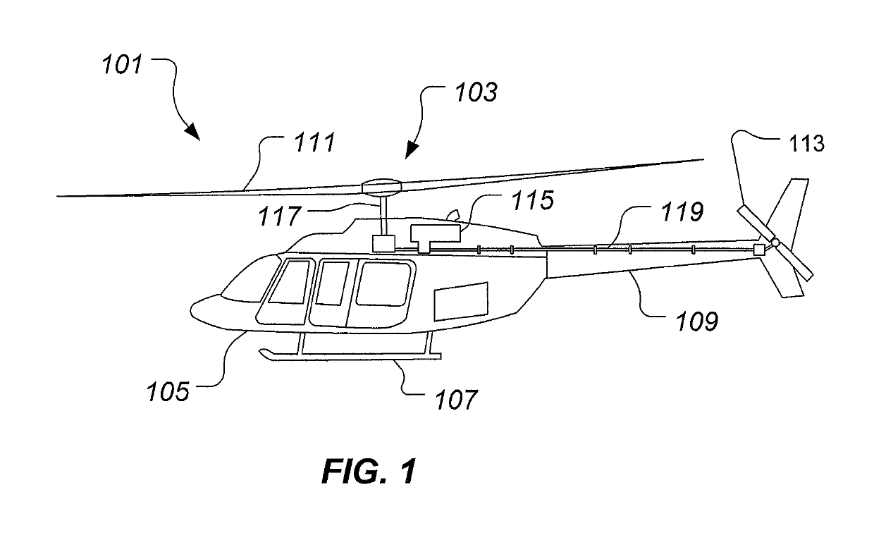
[0014]Illustrative embodiments of the system of the present application are described below. In the interest of clarity, not all features of an actual implementation are described in this specification. It will of course be appreciated that in the development of any such actual embodiment, numerous implementation-specific decisions must be made to achieve the developer's specific goals, such as compliance with system-related and business-related constraints, which will vary from one implementation to another. Moreover, it will be appreciated that such a development effort might be complex and time-consuming but would nevertheless be a routine undertaking for those of ordinary skill in the art having the benefit of this disclosure.

[0015]In the specification, reference may be made to the spatial relationships between various components and to the spatial orientation of various aspects of components as the devices are depicted in the attached drawings. However, as will be recognized by...


PUM


Abstract

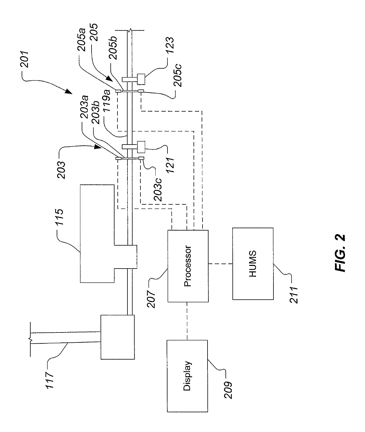
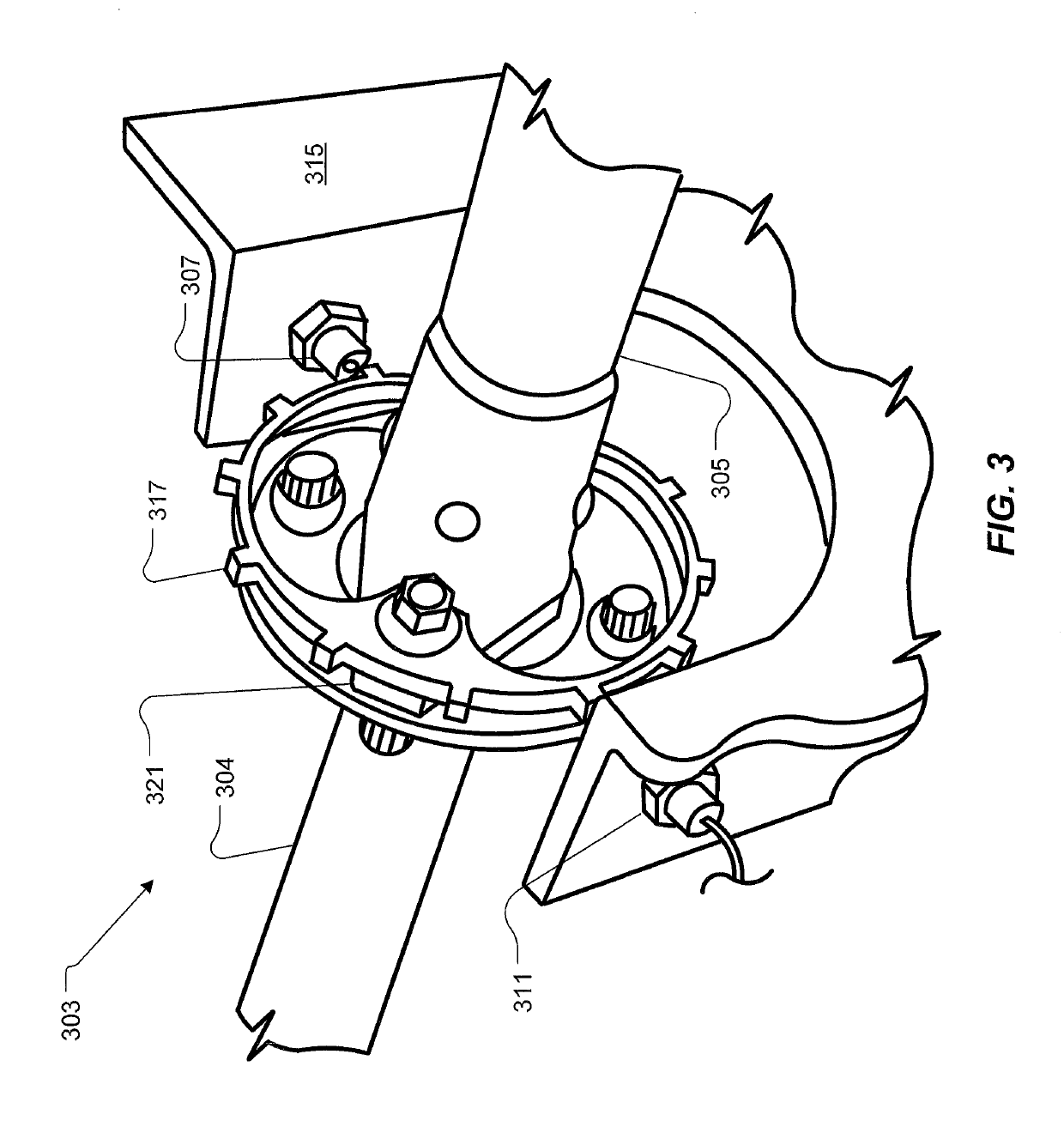
A method and apparatus for determining failure diagnosis of drive systems of rotorcrafts through measuring the spectral characteristics of rotational oscillations and torsional oscillations and steady windup of a drive shaft. Mechanical anomalies of the drive system will alter the spectral characteristics of rotational oscillations and torsional oscillations and steady windup as detected by a pair of variable reluctance sensors in conjunction with a radial grating mounted on the drive shaft.

Description

BACKGROUND[0001]Technical Field[0002]The system of the present application relates in general to the field of drive system health monitoring, and relates specifically to the drive systems rotational oscillations and torsional oscillations and steady windup and detection of mechanical anomalies indicated by these changes in rotational oscillations and torsional oscillations and steady windup of a series of drive shafts.[0003]Description of Related Art[0004]Typically, in rotorcrafts parts are replaced based upon the number of hours flown. Therefore, parts are inspected and replaced regularly to insure the aircraft is flightworthy. Instrumentation systems, based upon accelerometers, provide fault detection of drive trains. As the aircraft parts fail, harmonic analysis of the vibratory patterns changes and indicates a failing part. However, accelerometers must be spread out along the length of the drive train as vibrations resulting from faulty parts are generally localized to the fault...

Claims


Application Information

Patent Timeline
Patent Type & Authority Patents(United States)
IPC IPC(8): B64C27/00B64D45/00G01M15/12G01M13/02G01M17/007G01M13/028G01M13/045G01M17/00G01M15/04G01H1/00G01H11/02
CPCB64C27/006B64D45/00G01H1/003G01M13/028G01M13/045G01M15/12G01M17/00G01M17/007G01M15/042G01H11/02B64D2045/0085
Inventor HALE, RODNEY KEITHSPEARS, STEVEN KIRKTUCKER, BRIAN
Owner BELL HELICOPTER TEXTRON INC
Why Eureka
Try Eureka