Processing method for a rotation speed signal of an aircraft engine shaft affected by noise

a technology of rotating speed and noise, which is applied in the direction of machines/engines, mechanical equipment, instruments, etc., can solve the problems of reducing the useful signal measured amplitude, dephasing the useful signal, and allowing the measurement of the operating speed n1

Active Publication Date: 2020-11-10
SN DETUDE & DE CONSTR DE MOTEURS DAVIATION S N E C M A
View PDF9 Cites 0 Cited by
  • Summary
  • Abstract
  • Description
  • Claims
  • Application Information

AI Technical Summary

Problems solved by technology

However, the sinusoidal signal allowing measurement of the operating speed N1, produced by a phonic wheel sensor, can be very noisy.
However, the elimination of a frequency near the frequency of the useful signal causes dephasing of the useful signal.
This dephasing causes problems for certain possible uses of the measurement operational speed signal: in particular, the signal produced by the phonic wheel can be used for the function of engine balancing, if the phonic wheel is configured to supply an “impulse per revolution” allowing the elements of the engine to be keyed to the rotation of the shaft.
Moreover, low-pass filtration can reduce the measured amplitude of the useful signal, and increase the snapping threshold of the measurement (the threshold below which the rotation speed is not correctly measurable).
This effect is the more disturbing, the higher the ratio between the peak-to-peak amplitude of the measurement noise and the peak-to-peak amplitude of the useful signal.
Here too, however, the snapping threshold of the measurement is increased, and the accuracy of the measurement of the passage period of the teeth is affected, the more so if the ratio of the amplitude of the measurement noise and the amplitude of the useful signal is low.

Method used


Image

  • Processing method for a rotation speed signal of an aircraft engine shaft affected by noise
  • Processing method for a rotation speed signal of an aircraft engine shaft affected by noise
  • Processing method for a rotation speed signal of an aircraft engine shaft affected by noise

Examples


Embodiment Construction

[0036]In all the following, a processing method of a rotation speed measurement signal will be described, measured at the terminals of a phonic wheel sensor used for measuring the operating speed N1 of an engine. However, the same modalities of processing can also be advantageously used for measuring any other operating speed of a rotating element of the engine.

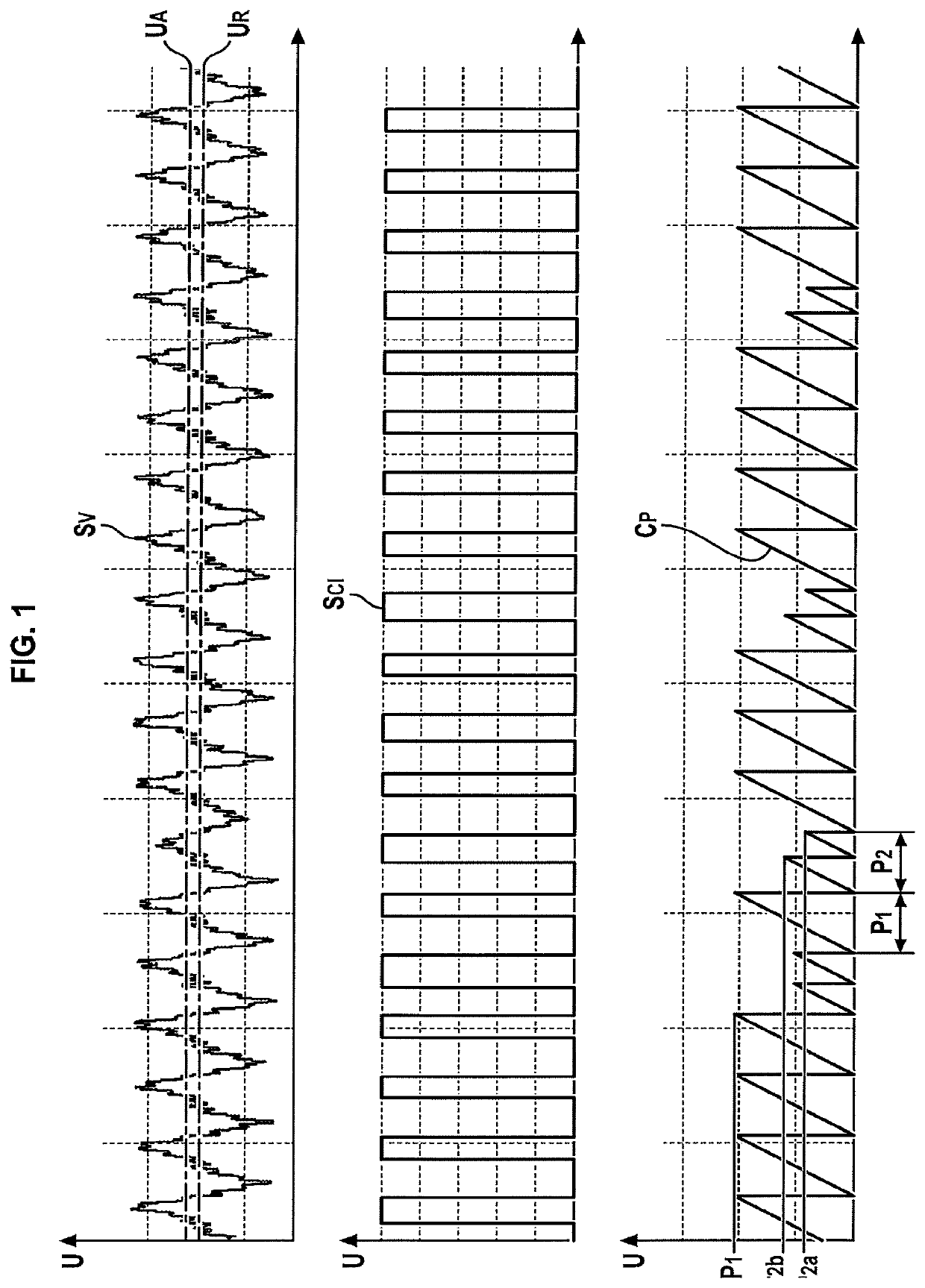
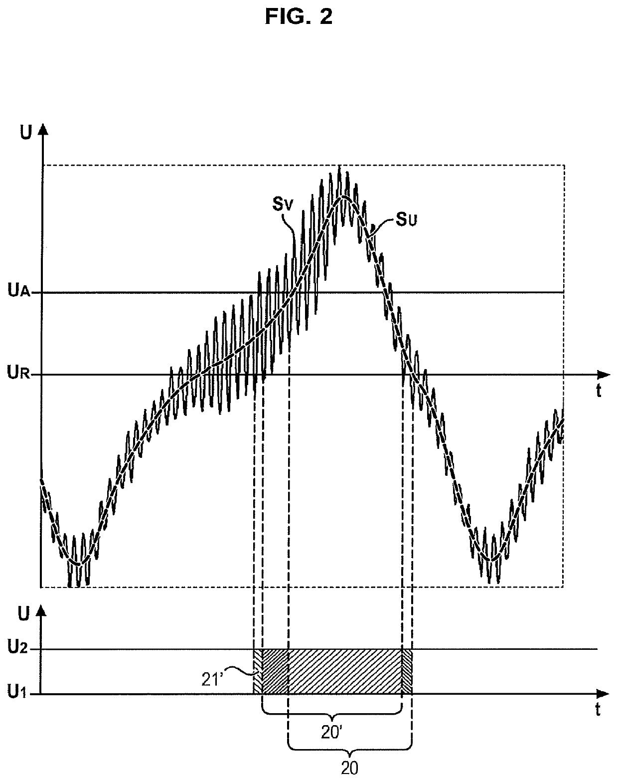
[0037]An alternating signal SV for detecting the rotation speed of the shaft of the low-pressure body (BP) of a two-spool turbojet is processed at the input of the engine computer (FADEC3 for example) to obtain a raw window signal SCI, on which a frequency measurement, allowing an operating speed value N1 to be derived, can be accomplished. For example, the signal SV can be filtered by an RC filter, then clipped, then filtered again, and finally windowed by a “Schmidt trigger” with a restart threshold UR of 0 V and with a reset threshold UA of 0.232 V. A first counter counts the descending fronts of a sample window signal wit...


PUM


Abstract

A processing method of an alternating signal produced by a variable reluctance sensor, including steps consisting of a raw window signal switching toward a low voltage level, respectively toward a high voltage level, calculation of a processed window signal using a value of the switching continuation duration calculated as a function of a value of shaft rotation speed, and based on the raw window signal, measurement of the shaft rotation speed, each switching of the processed window signal triggering the locking of the processed window signal, for a duration exactly equal to the switching continuation duration, so that the switches of the raw window signal are not translated into switches of the processed window signal during the locking, the processed window signal no longer being locked once the switching continuation duration has expired.

Description

TECHNICAL FIELD OF THE INVENTION[0001]The present invention relates to the measurement of the operating speed of rotating element of an aircraft engine, despite the existence of parasitic noise signals, produced by the activity of the engine.PRIOR ART[0002]For aircraft engines, it is important to dispose of accurate measurements of the rotation speed of the engine shaft. This information can control, for example, the cutoff or the regulation of the fuel supply to the engine, if the rotation speed or the acceleration exceed a predetermined value.[0003]It is well known to measure the rotation speed of a shaft using a electromagnetic type sensor associated with a phonic wheel. Hereafter this will be called a phonic wheel sensor, or else a variable reluctance sensor. The phonic wheel being driven by the shaft, the rotational movement of the phonic wheel is a function of the rotational movement of the shaft. The sensor creates, using a winding, a magnetic field which closes, either in th...

Claims


Application Information

Patent Timeline
Patent Type & Authority Patents(United States)
IPC IPC(8): G01P3/48G01P3/488F02C9/28G01P3/489
CPCF02C9/28G01P3/489G01P3/4802G01P3/488F05D2270/80F05D2220/323
Inventor DJELASSI, CEDRIK
Owner SN DETUDE & DE CONSTR DE MOTEURS DAVIATION S N E C M A
Why Eureka
Try Eureka