Perpetual calendar for a timepiece

a perpetual calendar and timepiece technology, applied in the field of timepieces, can solve the problems of loss of accurate display of date and (possible) day information, calendar date ring would have to be significantly readjusted, and become even more significan

Active Publication Date: 2006-04-11
TIMEX GROUP
View PDF12 Cites 4 Cited by
  • Summary
  • Abstract
  • Description
  • Claims
  • Application Information

AI Technical Summary

Benefits of technology

[0007]Accordingly, it is an objective of the present invention to provide a timepiece with an improved calendar function.
[0009]Another object of the present invention to provide an improved timepiece comprising a date and / or day display that utilizes stepping motors, such as bi-directional stepping motors, since by way of but one advantage, the use of stepping motors ensures correct driving angles from one date to the other without any additional required contact to stop the motor when rotation has to be terminated.
[0010]Another object of the present invention to provide an improved timepiece comprising a date and / or day display that is easy to adjust and furthermore, whereby the accuracy of the calendar date and / or day can be continuously and accurately maintained.
[0012]Still another object of the present invention is to provide an easier and faster way to set date and / or day displays in a timepiece that displays such information, especially in an analog timepiece.
[0013]Still another specific object of the present invention is to provide an improved timepiece comprising a day display which incorporates the use of a counter that allows for the maintaining of accurate relative day information.
[0015]And yet another object of the present invention to provide an improved timepiece comprising a date and / or day display that does not require the precision electrical contact reliability which is otherwise needed in prior art embodiments to even begin to achieve the advantages set forth herein.

Problems solved by technology

That is, in a conventional quartz analog timepiece, the stopping of the hour / minute hands typically results in an inability of the date ring from rotating, thus leading to a loss of accurately displayed date and (possibly) day information.
Moreover, if the hands are disengaged or otherwise stopped for a significant amount of time (e.g. days or weeks), any calendar date ring would have to be significantly readjusted (e.g. manually), a problem that becomes even more significant if the timepiece includes a month or day display or other perpetual calendar features.
Moreover, the perceived deficiencies with this construction are increased when one extends the functionality to the incorporation of a day disc, which during normal operation, rotates in synchronization with the hour hand.
Another deficiency in the prior art is the inability to adequately and accurately maintain (or update) the display of the proper day on a day ring, in the event that the hands of the timepiece are stopped.
Moreover, adjusting the day by a typical hand-setting operation thereafter will tend to further misadjust the date being displayed on the date ring since the typical synchronization between the hands and the date and day rings does not typically allow for independent calibration.

Method used


Image

  • Perpetual calendar for a timepiece
  • Perpetual calendar for a timepiece
  • Perpetual calendar for a timepiece

Examples


Embodiment Construction

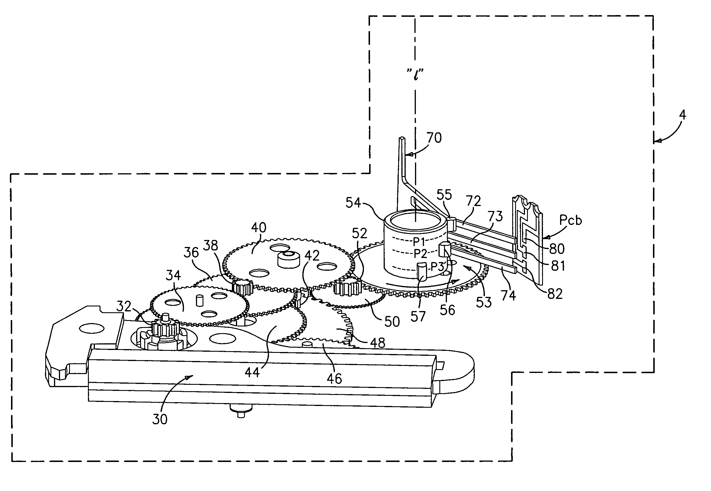
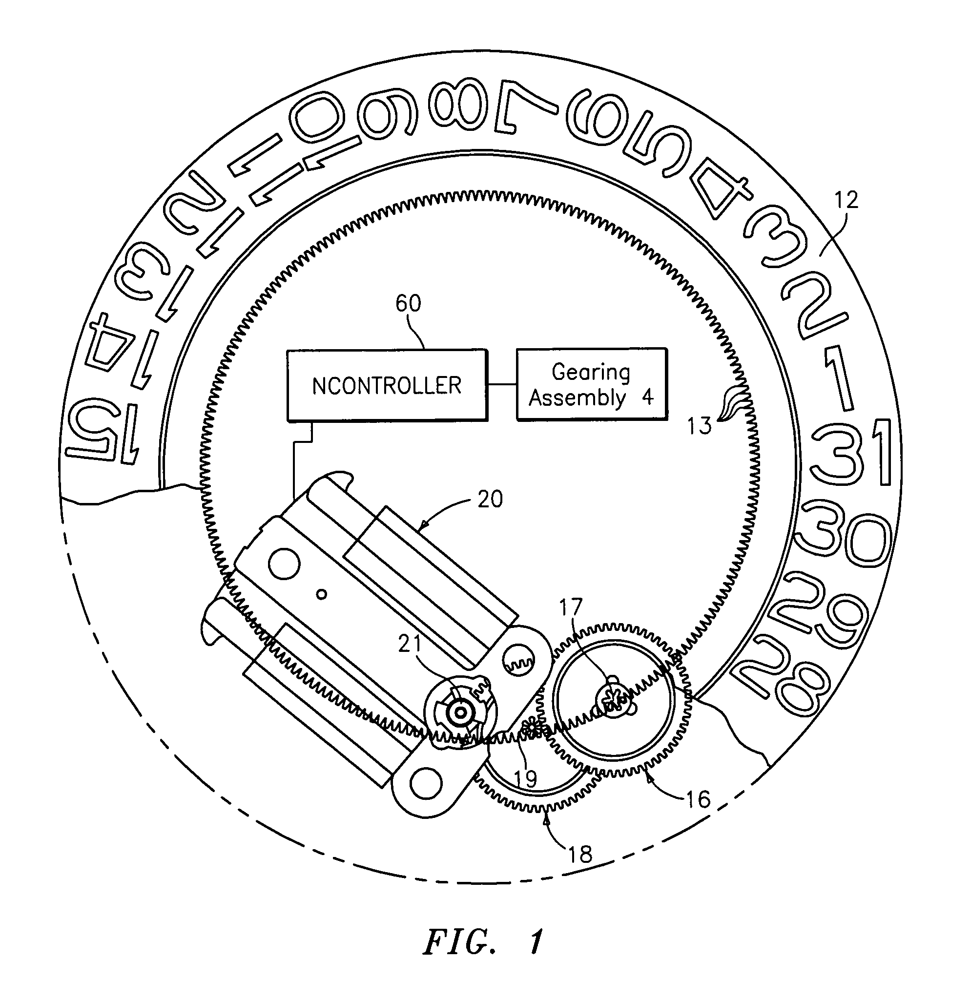
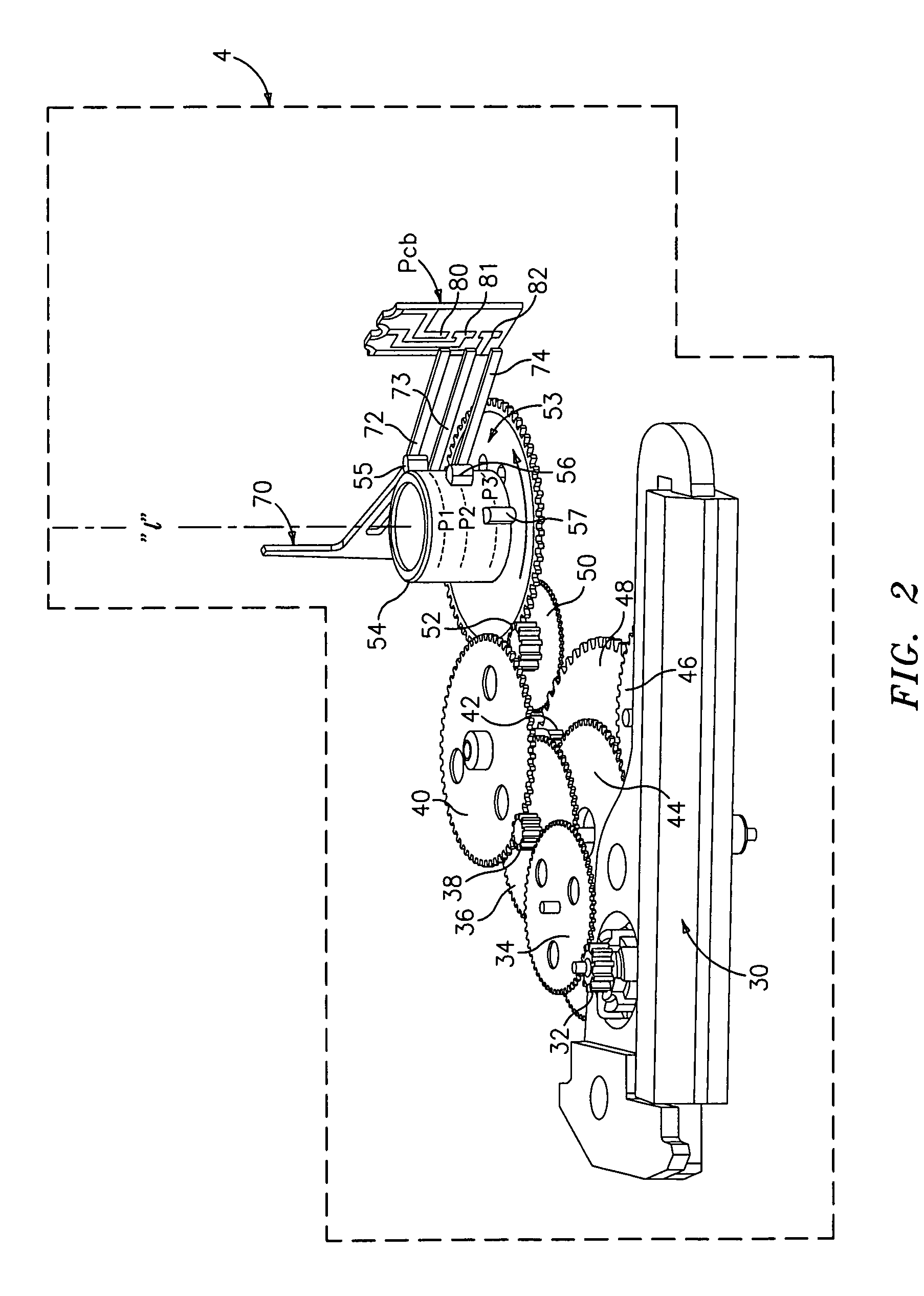
[0033]Reference shall first be made to FIGS. 1–6, wherein the relevant portions of a timepiece, generally indicated at 1 (and shown generally in FIG. 8) and including features of the present invention, is disclosed.

[0034]FIG. 1 most clearly illustrates a preferred construction of a date display assembly constructed in accordance with the present invention. Specifically, the date display assembly comprises a date ring 12, on which a plurality of digits (e.g. “1”, “2”, “3,” . . . “31”) may be printed, silkscreen, painted, or otherwise provided. Date ring 12 preferably has a plurality of teeth 13 on the inner circumference thereof for meshing with a gearing assembly which will now be disclosed.

[0035]Specifically, in the preferred embodiment, the gearing assembly for the date display assembly comprises one or more wheels. Illustrated in FIG. 1 is a date wheel 16 on which is a pinion 17, which is coupled to date ring 12 via teeth on pinion 17 being in meshing alignment with teeth 13 of d...


PUM


Abstract

A timepiece comprising a date display, comprising a date display assembly comprising a date ring, a first gearing assembly being meshingly coupled to the date ring for causing the rotation of the date ring; and a stepping motor comprising a rotor, wherein the rotor of the stepping motor is rotateably coupled to the at least one or more wheels of the first gearing assembly, wherein the rotation of the rotor causes the date ring to rotate; a date-keeping assembly operatively coupled to the date display assembly, comprising: at least a second gearing assembly comprising at least an hour wheel and a detection wheel assembly, wherein at least certain rotational increments of the detection wheel, and the clockwise or counterclockwise direction thereof, causes the rotor of the stepping motor to rotate so that the date ring can be rotated in one of a clockwise or counterclockwise direction; whereby the rotation of the hour wheel through a predetermined midnight position results in that the stepping motor causes the date ring to rotate a predetermined number of degrees, thereby advancing either in the forward or backward direction a displayed digit on the date ring representing a valid date. Methodologies for setting and adjustment are also provided.

Description

BACKGROUND OF THE INVENTION[0001]The present invention relates generally to timepieces, such as wristwatches, and in particular, to improved constructions and methodologies for maintaining accurate date and / or day information, in such timepieces that comprise a date and / or day ring, such as those timepieces typically referred to as “analog” or “quartz-analog” watches having hands for displaying time, and which drive the date ring as a function of the rotation of one or more gears (or “wheels”), such as (by way of example) the wheel that is coupled to the hour hand. In particular, the present invention provides an improved construction and methodology for maintaining an accurate date and / or day display even if the hour / minute hands are mechanically and / or electrically decoupled from the date display assembly.[0002]That is, in a conventional quartz analog timepiece, the stopping of the hour / minute hands typically results in an inability of the date ring from rotating, thus leading to ...

Claims


Application Information

Patent Timeline
Patent Type & Authority Patents(United States)
IPC IPC(8): G04B19/20G04B19/24G04BG04C17/00
CPCG04C17/0066
Inventor BURKHARDT, WOLFGANGGALIE, LOUIS M.PLANCON, MICHEL G.ZACHMANN, HELMUTSTOTZ, GERHARDGRAU, SIEGFRIED
Owner TIMEX GROUP
Why Eureka
Try Eureka