Distributed port-blocking method

a technology of port blockage and distribution, applied in the field of communication networks, can solve the problems of increasing the probability of failure, the impact of the complexity of the device, so as to reduce the number of possible operability changes

Inactive Publication Date: 2006-04-11
LUCENT TECH NETWORKS
View PDF7 Cites 67 Cited by
  • Summary
  • Abstract
  • Description
  • Claims
  • Application Information

AI Technical Summary

Benefits of technology

[0045]Preferably, determining the topology information includes determining whether one or more links of the network are operative. Preferably, determining the one or more parameters of the network includes determining weights of one or more links of the network. Preferably, changing at least one of the one or more parameters of the network includes changing the weight of at least one of the links of the network. Preferably, changing the weight of the at least one of the links includes reducing the weight of at least one currently active link of the network.
[0048]Preferably, changing at least one of the one or more parameters of the network includes reducing the number of possible operability changes which will change the group of blocked ports of the network by changing the at least one of the one or more parameters of the network.
[0049]Alternatively or additionally, changing at least one of the one or more parameters of the network includes preventing the group of blocked ports of the network from changing without a failure occurring on the connection of an active port by changing the at least one of the parameters.

Problems solved by technology

For example, the disconnection, even for a short period, of some Internet, banking, telephone and stock market servers may have severe economical consequences.
As with other complex devices, bridging-devices and communication links may fail.
Usually, the chances of a failure occurring increase with the complexity of the device.
If the network includes a loop of ports, a single frame may be repeatedly forwarded through the network and the network will fail.
In such a configuration it is not possible to use the method described in the Ori Bendori paper, as a single port connects the end-station to the bridging-devices.
For example, in some cases it is not practical to change the end-station devices to operate in accordance with special, fast, port blocking methods.
In some cases a failure of a device or link may be partial, for example, a link may operate only in one direction and not in the other direction.
Existing blocking methods do not always detect such partial failures.
These hardware tests, however, do not catch all the possible problems which could cause the connection between two devices to be inoperative.
Thus, in some cases messages are not properly transmitted from one bridging-device to the other although the hardware indicates the link is operative.
Using the indications of the hardware may result in wrong operation of the STA in activating a port which should be blocked, which may cause a broadcast storm, or in blocking a port which should be active which results in a network disconnection.
For example, if both the bridging-devices do not receive hello messages from each other due to a fault in the link, and the hardware does not detect the fault, both the bridging-devices may assume the other bridging-device is faulty and activate their ports.
When the fault disappears a loop is formed and the network may suffer from a broadcast storm.
A broadcast storm may also result if a link operates only in one direction and the problem is not identified by the hardware.
This, however, causes an extra, unnecessary, switch of the network which interrupts the data flow in the network.

Method used


Image

  • Distributed port-blocking method
  • Distributed port-blocking method
  • Distributed port-blocking method

Examples


Embodiment Construction

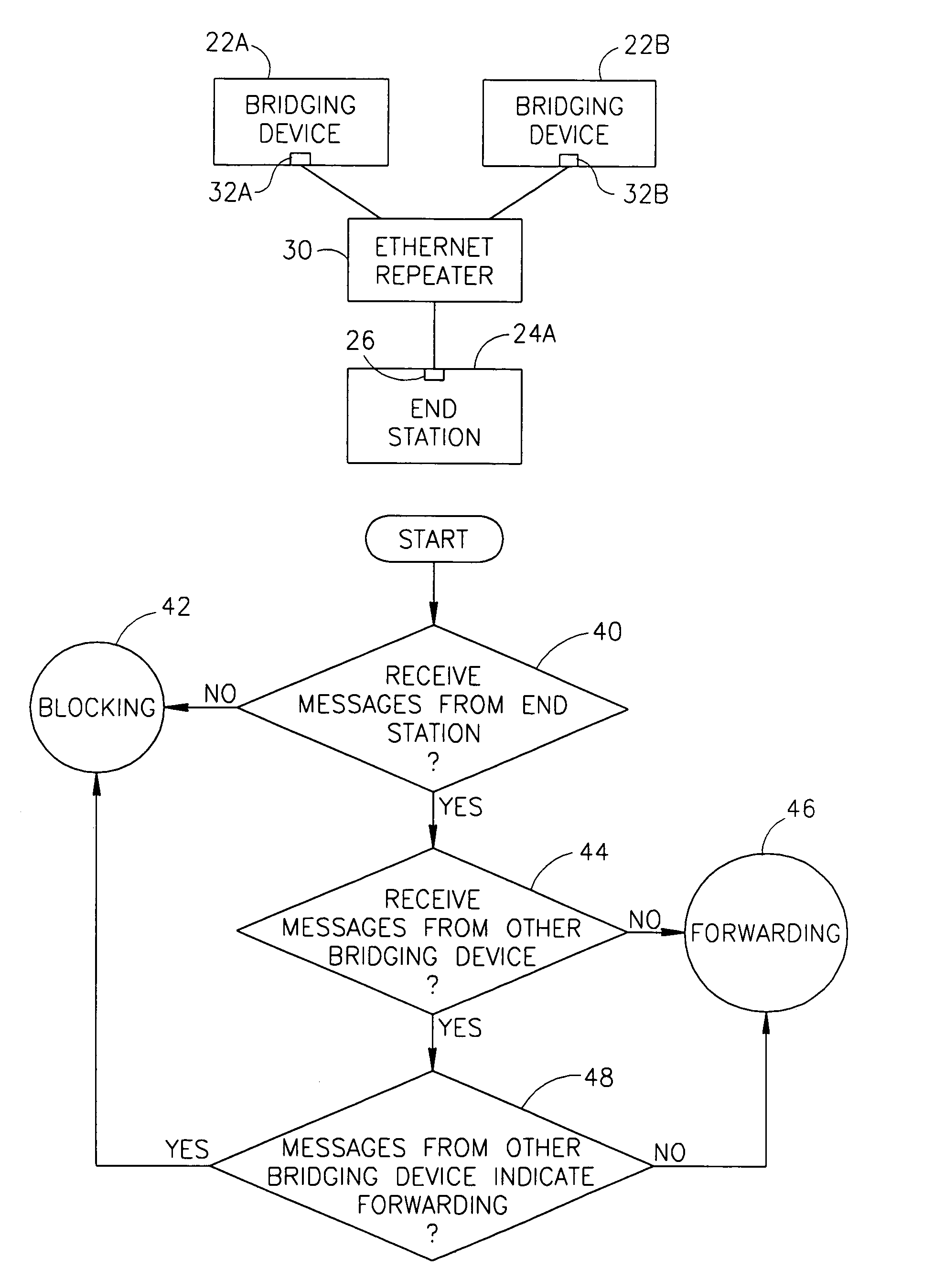
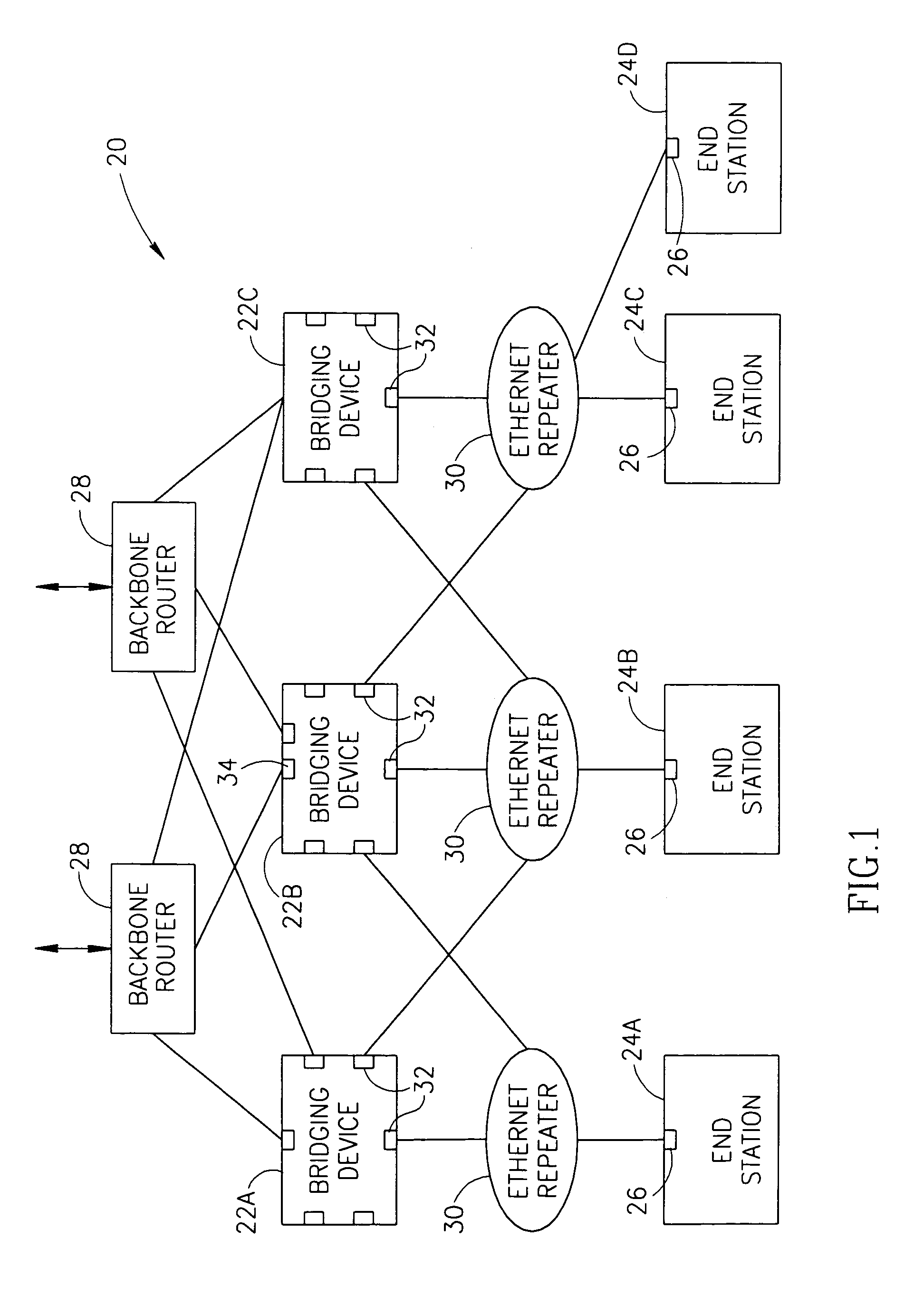
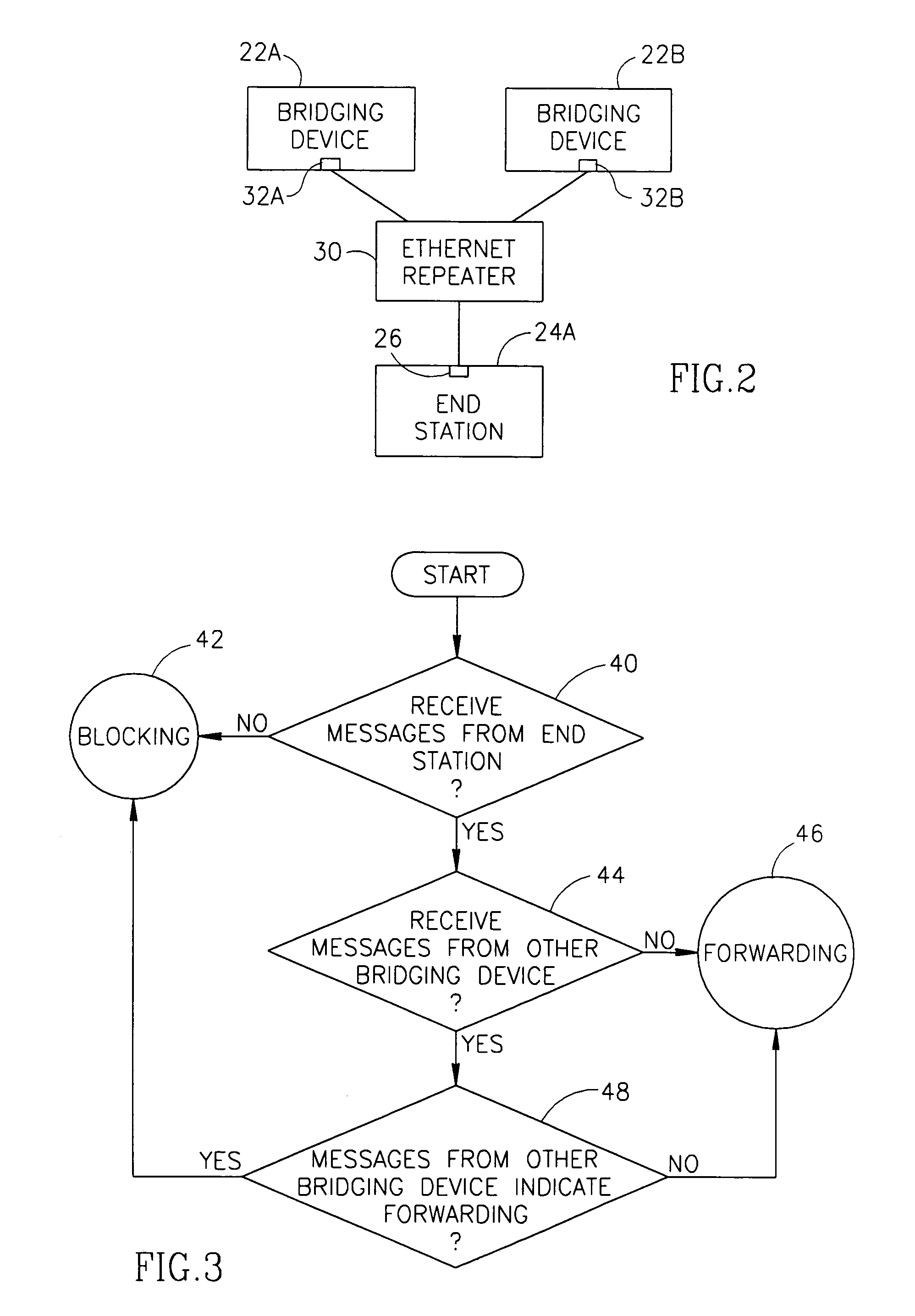
[0063]FIG. 1 is a schematic illustration of a local area network 20, in accordance with a preferred embodiment of the present invention. Network 20 comprises a plurality of bridging-devices 22 which are used to connect a plurality of end-stations 24 (marked in FIG. 1 as 24A, 24B, 24C and 24D) to each other and / or to external networks, through one or more backbone bridging-devices and / or routers, such as a pair of backbone bridging-devices which are also routers, referred to as backbone routers 28 in FIG. 1. One or more of end stations 24 comprise only a single port 26 which is suitable for connecting to any of bridging-devices 22. Preferably, the ports 26 of end-stations 24 are connected through respective Ethernet repeaters 30 to a plurality of ports 32 on different bridging-devices 22. Thus, redundancy is achieved in connecting end-stations 24 to bridging-devices 22, even though each end-station 24 has only a single port 26. It is noted that one or more of repeaters 30 may be repl...


PUM


Abstract

A method of managing connectivity between an end-device and one of a plurality of bridging-devices connected to the end-device. The method includes transmitting test messages by each of the bridging-devices, transmitting test messages by the end-device, determining, in each of the bridging-devices, with which of the other devices there is an operative connection, based on the test messages the bridging-device receives and determining, in each of the bridging-devices, whether a port leading to the end-device should be in a forwarding or blocking state responsive to the determination of the operative connections.

Description

RELATED APPLICATIONS[0001]The present application is a continuation in part of U.S. patent application Ser. No. 09 / 061,484, filed Apr. 16, 1998, now abandoned, to Lior Shabtay, titled “Apparatus and method for Managing Communication Networks”, the disclosure of which is incorporated herein by reference.FIELD OF THE INVENTION[0002]The present invention relates to communication networks and in particular to local area networks with redundancy.BACKGROUND OF THE INVENTION[0003]Generally, local area networks are used to connect a plurality of end-stations, e.g., computers, to each other and / or to one or more gateways which lead to wide area networks. In many cases the connections of the end-stations to each other and / or to a wide area network are very important and should not fail even for a few seconds. For example, the disconnection, even for a short period, of some Internet, banking, telephone and stock market servers may have severe economical consequences.[0004]Local area networks g...

Claims


Application Information

Patent Timeline
Patent Type & Authority Patents(United States)
IPC IPC(8): H04L12/26
CPCH04L12/4625
Inventor SHABTAY, LIORISLAND, MOSHECOHEN, NACHMANKRONENTHAL, GUYSALTZMAN, MICHAELNAVON, GIDIBIN, RON
Owner LUCENT TECH NETWORKS
Why Eureka
Try Eureka