Method and apparatus for splicing

a technology of splicing and splicing, applied in the field of digital image data processing, can solve the problems of affecting video quality, affecting video quality, and affecting the shape of operation complexity, so as to avoid the introduction of discontinuities in clocks and less computing capacity

Inactive Publication Date: 2006-04-11
PINNACLE SYSTEMS
View PDF12 Cites 66 Cited by
  • Summary
  • Abstract
  • Description
  • Claims
  • Application Information

AI Technical Summary

Problems solved by technology

The advantages, however, are balanced with drawbacks in the shape of operational complexity.
This is, however, comparatively costly and has a severe impact on video quality.
Consequently, until the problem is solved in a more satisfactory manner, the broadcasting industry and consumer networks will have no option but to remain analogue and many opportunities for new digital services will be stalled.
If splicing rules are not observed the MPEG standard will be violated resulting in unpredictable performance by a decoder.
Distracting and highly noticeable artefacts may occur, which can continue for an extended period while image data buffers are flushed of undecodable data and the decoder re-synchronises.
Other problems faced when splicing according to prior art is quality loss due to alterations of the information in the video layer or due to adjustment of DCT quantization or such manipulation
A problem connected to the processing of compressed video streams; and especially splicing programs comprising video, is that, unlike uncompressed video, picture boundaries in the bitstream are not evenly spaced.
In practice, this entails a reduction in bit rate or a restriction in the GOP structure near the splice points, which in turn results in decreased video coding efficiency and a system layer overhead.
One drawback with this technique is that the required pre-processing of program material is costly, and another drawback is the fact that practically all existing program material already encoded into the MPEG domain will be impossible to splice.
A further drawback is that existing encoders and multiplexers cannot be used with pre-processed material, and have to be replaced.

Method used


Image

  • Method and apparatus for splicing
  • Method and apparatus for splicing
  • Method and apparatus for splicing

Examples


Embodiment Construction

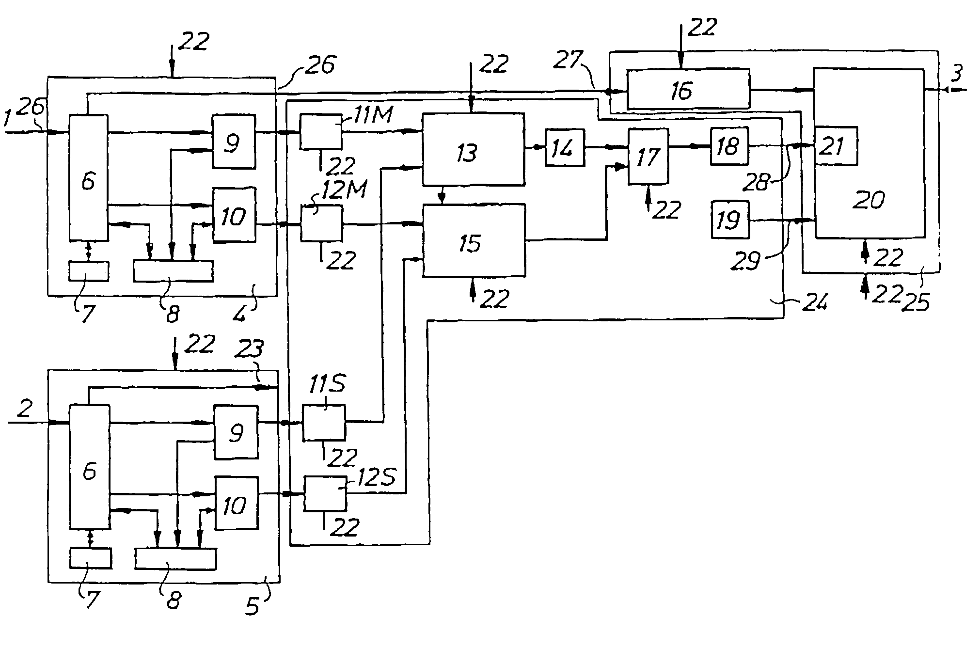
[0042]The splicing method and system according to the invention, hereinafter also called the splicer referring to the method as well as to the apparatus, is intended to be used for seamless splicing of image data streams in the MPEG domain. The splicer receives as an input one or more source MPEG transport streams (TS), and delivers as an output one or more resulting MPEG transport streams.

[0043]In one embodiment of the invention the splicer is applied in a local network station. This local network would typically receive TS:s from different national broadcasters as well as local TS:s. There may also be a selectable input of TS:s from hardware in the network station.

[0044]The problem of splicing concerns the problem of interleaving one stream of data, i.e. video, audio, etc, in an MPEG transport stream (TS) with another stream of the same kind of data in the same TS or in another TS. Isolated bits of data strongly associated to each other constitute a frame. In the video case, for i...


PUM


Abstract

A method and apparatus for splicing programs in the MPEG domain, wherein program data is carried in MPEG transport streams (TS) of data packets. The data packets carry application data, e.g. video and audio data, and a header provided with control data. According to the invention control data objects are established for each data packet for storing time references and data packet status information. The control data objects are queued in different queues dependent on the data packet status or on the status of a group of data packets. Control data objects associated to data packets to be output in an output stream of data packets are selected from the queues, whereupon selected control objects are assembled to a program of associated data packets of different kinds of data. Finally, data packets associated to said selected and assembled control data objects are assembled to an output stream of data packets.

Description

[0001]This is a continuation of International Application Serial No. PCT / SE99 / 01177, filed Jun. 29, 1999, the entire disclosure of which is incorporated herein by reference.TECHNICAL FIELD[0002]The present invention relates generally to processing of digital image data, and in particular to a method and a system for concatenating or splicing streams of digital data comprising image data compressed in accordance with MPEG as well as other data.BACKGROUND[0003]Digital compression technology has brought considerable benefits in terms of bandwidth savings and the potential for improved image quality when telecommunicating or telecasting. The advantages, however, are balanced with drawbacks in the shape of operational complexity. A simple video manipulation such as a cut between two sources is considerably more complex in the MPEG domain than with uncompressed analogue data due i.a. to an interdependence between data in an MPEG encoded data stream.[0004]A state of the art solution in the...

Claims


Application Information

Patent Timeline
Patent Type & Authority Patents(United States)
IPC IPC(8): H04B1/66H04N7/24
CPCH04N21/23406H04N21/23424H04N21/44016H04N21/23611H04N21/44004H04N21/23608
Inventor ANDERSON, ROGERFARM, LARS
Owner PINNACLE SYSTEMS
Why Eureka
Try Eureka