Supercharge Your Innovation With Domain-Expert AI Agents!

Tubular expansion apparatus and method

a technology of tubular expansion and swedge cone, which is applied in the direction of drilling casings, drilling pipes, borehole/well accessories, etc., can solve the problems of unsuitable open hole applications, unsuitable for open hole applications, and the use of fixed-diameter swedge cones is somewhat impractical, so as to avoid hanging up on removal and raise the gas pressure

Inactive Publication Date: 2006-04-18
BAKER HUGHES INC
View PDF23 Cites 28 Cited by
  • Summary
  • Abstract
  • Description
  • Claims
  • Application Information

AI Technical Summary

Benefits of technology

The patent describes tools used to expand downhole tubulars in each other or in open hole. One tool uses a movable cone to push collets out to a predetermined maximum diameter, while a release system allows for collet retraction to prevent hang up on removal. Another tool uses pressurized gas to push the movable cone against the collets, which raises the gas pressure when forced in. A pressure actuated release allows for the collets to retract for removal. These tools help to expand downhole tubulars and improve the process of drilling and wellbore construction.

Problems solved by technology

Because of this, there is a problem with using a cone that is driven into a tubular to expand it into a given casing size.
In open hole the same problem can arise, as well as other problems.
An open hole borehole however usually is not consistent in diameter and shape, and may consist of washed out areas as well as sections that may have partially collapsed inward.
This makes the use of a fixed-diameter swedge cone somewhat impractical for open hole applications, as it does not have the capacity to adjust with irregularities in the borehole.
A fixed-diameter swedge cannot compensate for enlarged holes to provide the borehole wall-to-liner contact, and may prohibit passage through the liner / screen when encountering a collapsed area in the borehole.
This can create potential hang up problems on the removal operation after expansion.
This design makes it difficult to adjust the preload on the Bellville washers.
Mechanical drive mechanisms, while perhaps simpler, are impractical due to the relatively large axial displacement of the upper drive cone during normal operations of the device (i.e. a Belleville spring stack would be impractically long to allow for such high axial movement at the desired force for liner / screen expansion).
A coiled spring would simply be too big in diameter for the available space and the force delivery requirement.
Also, this same process occurs if a collapsed section of the borehole is encountered.

Method used


Image

  • Tubular expansion apparatus and method
  • Tubular expansion apparatus and method
  • Tubular expansion apparatus and method

Examples


Embodiment Construction

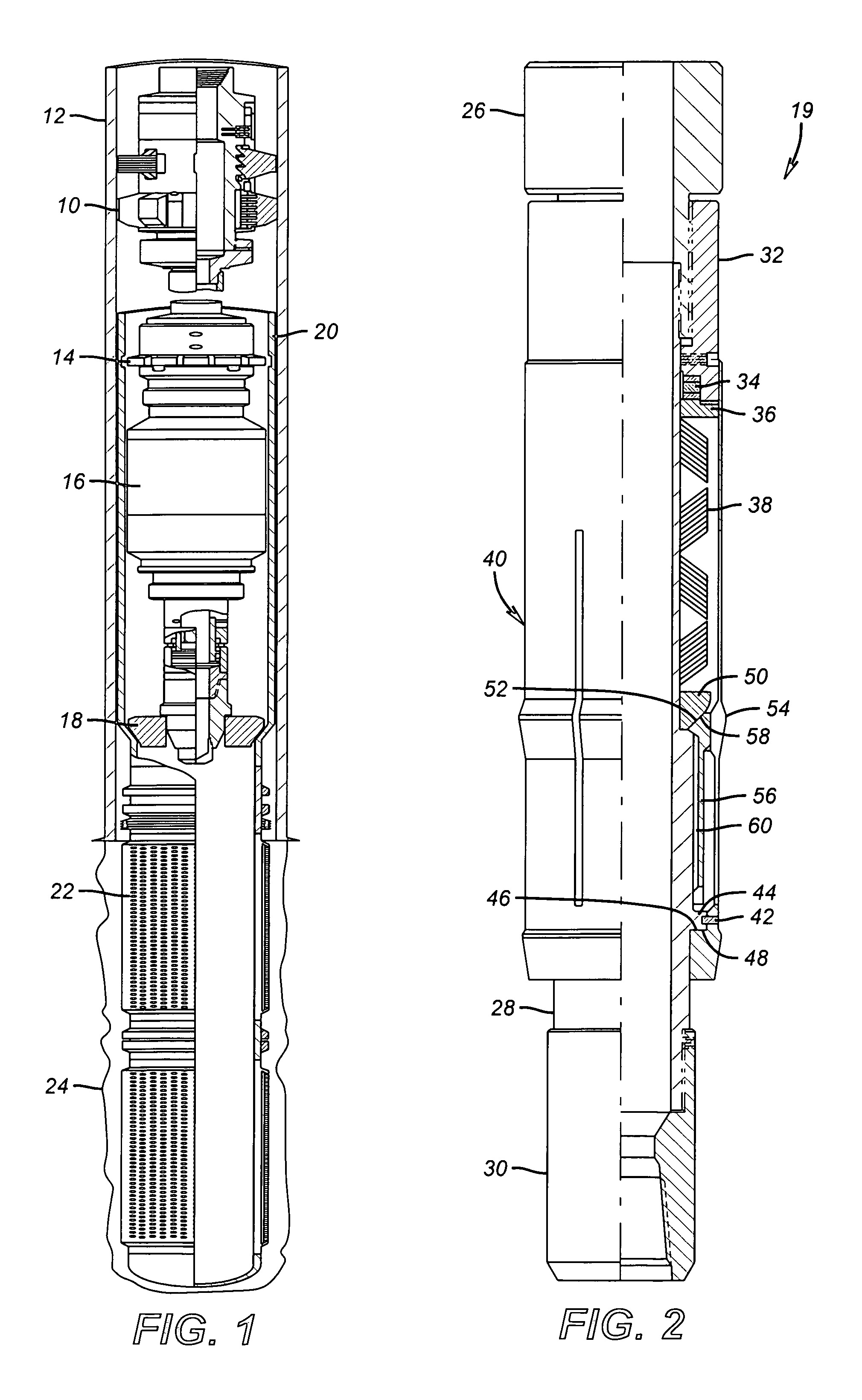
[0018]FIG. 1 generally shows the components of a one-trip system for expansion of tubulars downhole. An anchor 10 is set in casing 12. Below the anchor 10 is the liner running tool 14, which is in turn connected to the hydraulic drive assembly 16. The drive assembly 16 advances the swedge cone 18 to expand the blank pipe 20, with anchor 10 selectively engaged to the casing 12. Mounted below the blank pipe 20 can be screens 22 (shown prior to expansion), or a combination of screens with additional blank pipe between screen sections, in the open hole 24 section of the borehole. Generally, “tubulars” as used herein is intended to cover tubes, whether solid or having openings, liners, and screens.

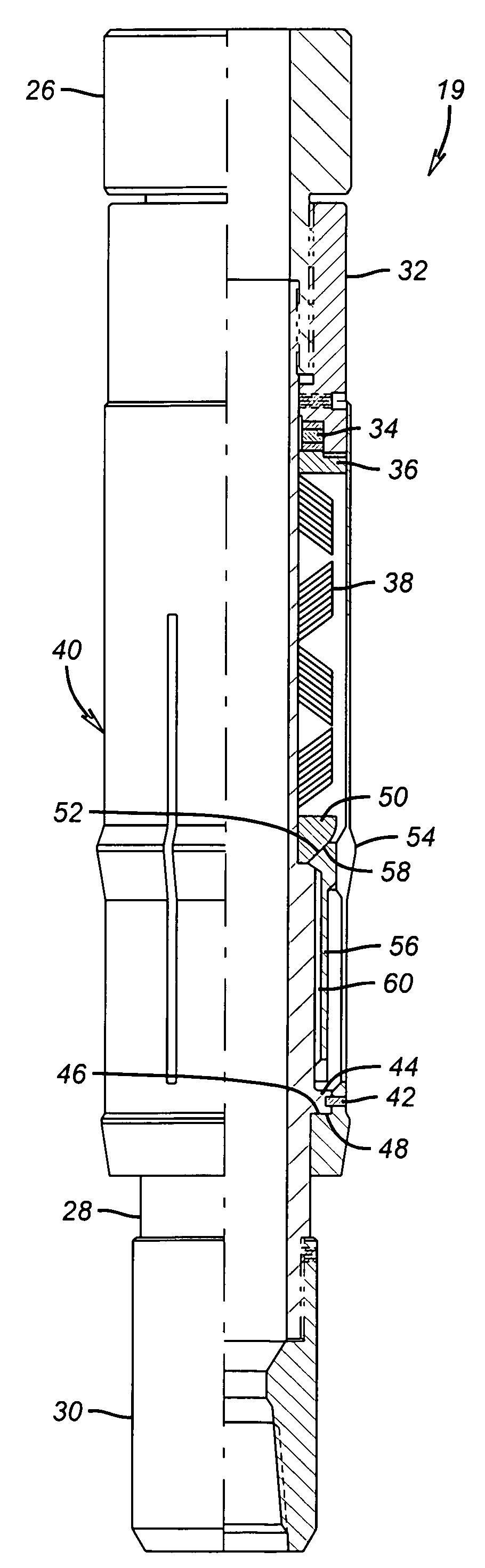
[0019]Referring to FIG. 2, an embodiment more particularly suited to expansion of blank pipe 20 in casing 12 is shown. Tool 19 has a top connection 26, which is attachable to the hydraulic drive assembly 16, such as shown schematically in FIG. 1. Top connection 26 is connected to body 28, which...


PUM


Abstract

Tools for expanding downhole tubulars into each other or in open hole are disclosed. One embodiment uses a movable cone biased by Bellville washers to move longitudinally against such bias and allow collets to move radially in or out to a predetermined maximum diameter. A release system allows collet retraction to avoid hang up on removal. In an alternate embodiment, more suitable for open hole applications, pressurized gas pushes a movable cone longitudinally against the collets. A stationary cone is on the opposite side of the collets from the movable cone. The collet rides out or in between the cones and raises the gas pressure when forced in. A pressure actuated release allows the lower cone to shift downwardly to allow the collets to retract for removal.

Description

PRIORITY INFORMATION[0001]This application claims the benefit of U.S. Provisional Application No. 60 / 326,364 on Oct. 1, 2001.FIELD OF THE INVENTION[0002]The field of this invention relates to expansion of tubulars into other tubulars downhole or in open hole using liners, screens or tubing, both as a method and the specific equipment, which can be used to accomplish the method.BACKGROUND OF THE INVENTION[0003]In the past, tubulars have been expanded into casing for the purposes of patching broken casing or to hang a liner string. The casing, in different applications can have different wall thickness for a specific casing size, depending on the particular well requirements. Because of this, there is a problem with using a cone that is driven into a tubular to expand it into a given casing size. If the wedge or cone is a fixed dimension, it can hang up in heavy wall casing, where the need to expand the tubular is less than if the casing had a thinner wall.[0004]In open hole the same ...

Claims


Application Information

Patent Timeline
Patent Type & Authority Patents(United States)
IPC IPC(8): E21B23/00E21B43/10
CPCE21B43/105E21B43/103E21B43/02E21B29/00
Inventor SMITH, JR., SIDNEY K.CORONADO, MARTIN P.TOM, ANDYHO, VAN N.KARA, FATIH M.
Owner BAKER HUGHES INC
Features
  • R&D
  • Intellectual Property
  • Life Sciences
  • Materials
  • Tech Scout
  • Unparalleled Data Quality
  • Higher Quality Content
  • 60% Fewer Hallucinations
Learn More