Closure element, especially a valve cone for a continuous pressure valve

a continuous pressure valve and valve cone technology, applied in the field of closing elements, can solve the problems of no centering bore for grinding between centers, and the cost of both production variants is high, and the centering bore is not admissible directly

Inactive Publication Date: 2006-04-18
BOSCH REXROTH AG
View PDF17 Cites 16 Cited by
  • Summary
  • Abstract
  • Description
  • Claims
  • Application Information

AI Technical Summary

Problems solved by technology

Both production variants are therefore very costly.
When round material is used, the valve cones, on account of the overflow flats, must be set up for individual grinding operations, either in order to subsequently provide the sealing and guide sections, ground in a centerless manner in a preceding operation, with flats in the region of the guide section, or in order to grind the guide section of the valve cone already provided with flats and the sealing section in two separate operations, since simultaneous centerless grinding of guide and sealing sections is not possible on account of the flats.
However, no centering bore for grinding between centers is admissible directly at the contact surface between the valve cone and a plunger interacting with the latter.

Method used


Image

  • Closure element, especially a valve cone for a continuous pressure valve
  • Closure element, especially a valve cone for a continuous pressure valve
  • Closure element, especially a valve cone for a continuous pressure valve

Examples


Embodiment Construction

[0010]The same parts are provided with the same reference numerals.

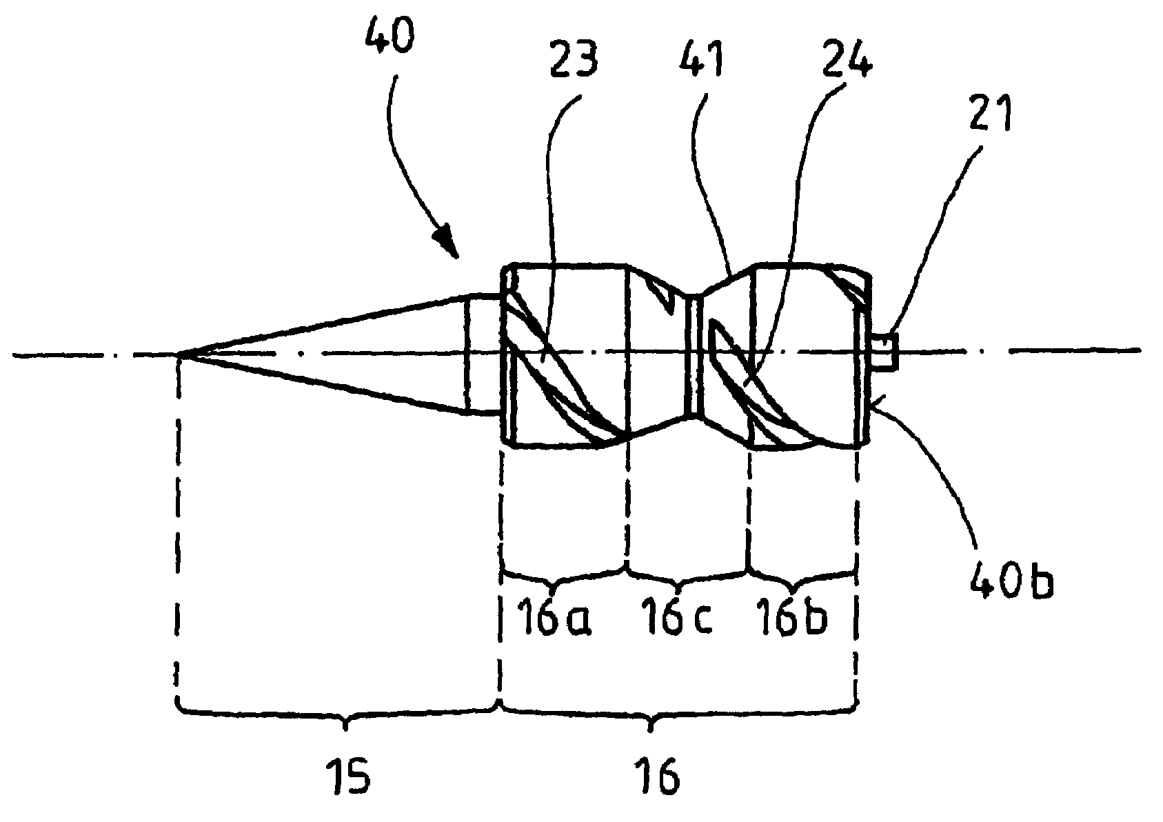
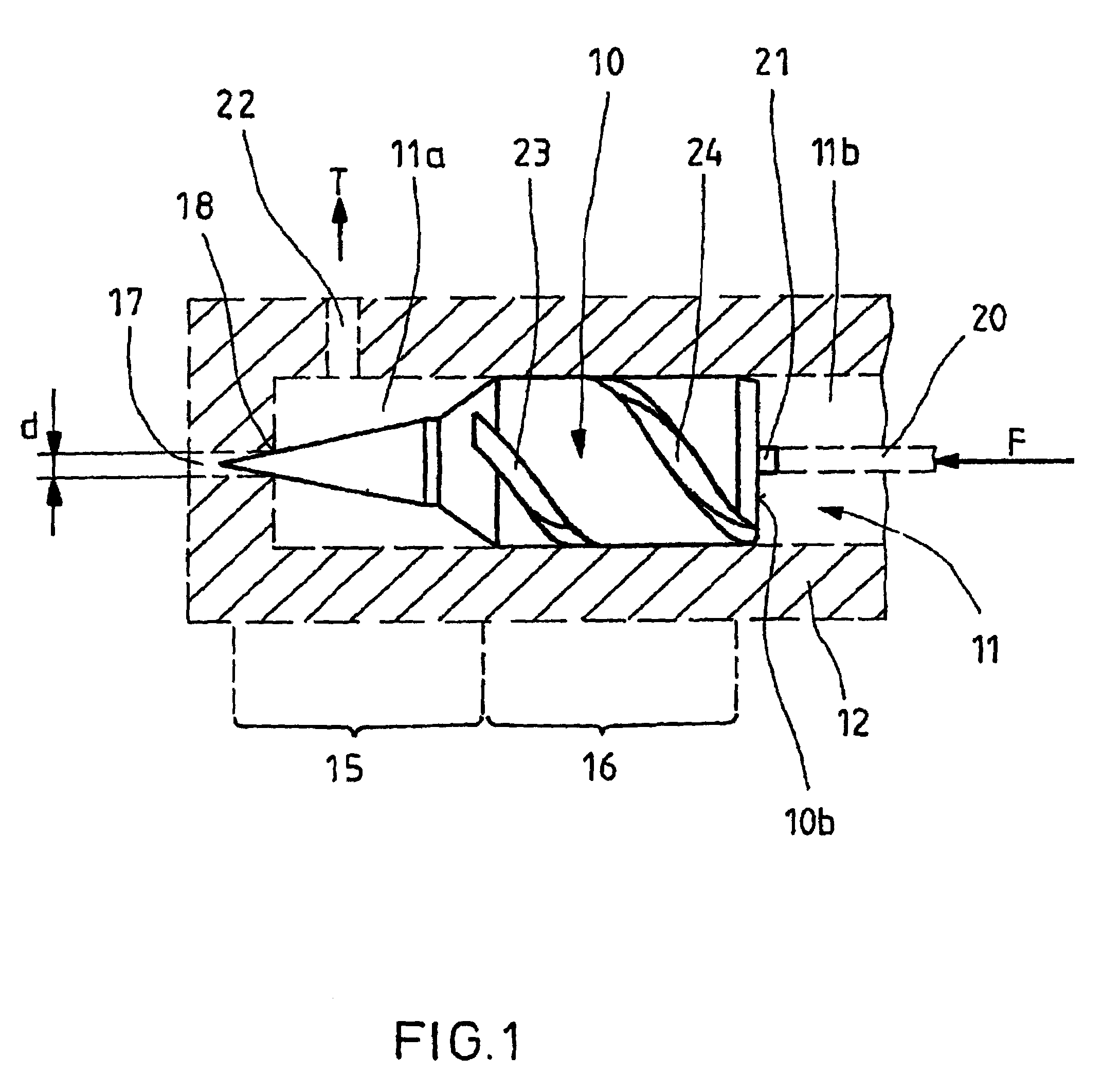
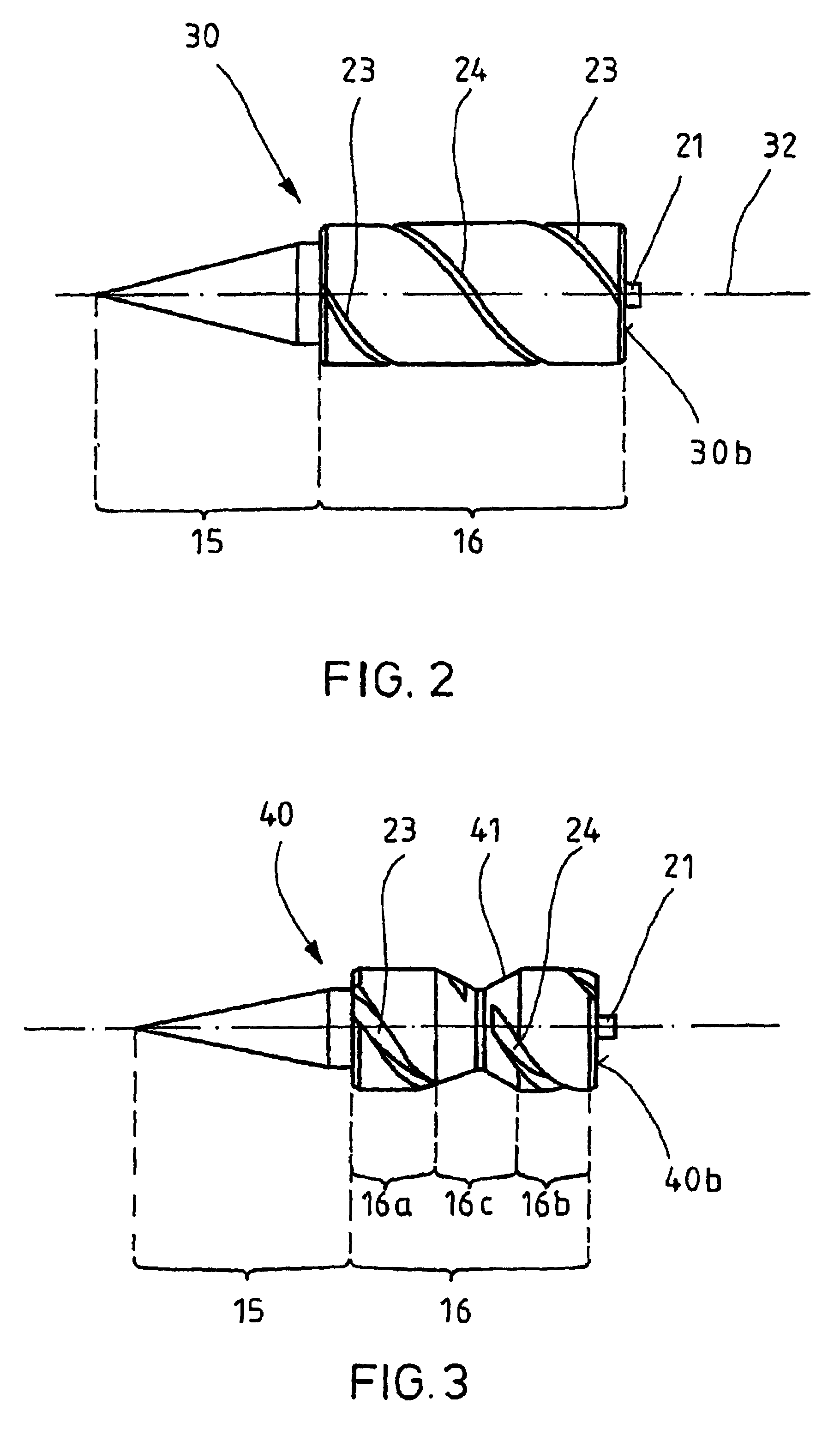
[0011]FIG. 1 shows a first closing body configured according to the invention in the form of a valve cone 10 which is guided in a bore 11 of a housing 12 (only schematically shown) of a hydraulic valve. The valve cone 10 subdivides the bore 11 into two regions 11a and 11b. The valve cone 10 has a conically formed sealing section 15 and a cylindrically formed guide section 16. The tip of the conically formed sealing section 15 projects into a bore 17 of the valve 12, via which bore 17 the pressure medium is fed to the valve 12. The outlet opening of the bore 17 is formed as a valve seat 18. A choke gap controlling the pressure medium flow is formed between the valve seat 18 and the conically formed sealing section 15 of the valve cone 10. The size of the choke gap is determined by the distance of the valve cone 10 from the valve seat 18. The pressure medium exerts a force on the valve cone 10 which is equal to the pro...


PUM


Abstract

A closing body is mounted in an axially displaceable manner in a bore of a fluidic valve to control a pressure medium flowing via the valve. The closing body has a sealing section, interacting with a seating edge of valve, and a guide section which serves to guide the valve cone in the bore. The guide section is provided with recesses which allow an overflow of pressure medium between the two sides of the closing body. To reduce costs of production, the guide section of the closing body is of cylindrical form and its surface is provided with at least one helical groove which leads from one side of the guide section to its other side. The closing body is useful in particular in constant pressure valves for controlling fluid pressure medium. The sealing section of the closing body is normally of conical form.

Description

FIELD AND BACKGROUND OF THE INVENTION[0001]The invention relates to a closing body, in particular a valve cone for a constant pressure valve, for controlling fluidic pressure medium, having a sealing section and a guide section which allow an overflow of pressure medium between the two sides of the closing body.[0002]Such a closing body formed as a valve cone has been disclosed by DE 199 07 732 A1. The valve cone is mounted in an axially displaceable manner in a bore of a directly actuated hydraulic proportional pressure relief valve. It has a conically formed sealing section and a guide section. The tip of the sealing section interacts with a seating bore. Formed between the outlet opening of the seating bore and the conically formed sealing section is a choke gap which controls the pressure medium flow and the size of which depends on the position of the valve cone. The guide section has two subsections which guide the valve cone and between which a further section of smaller diam...

Claims


Application Information

Patent Timeline
Patent Type & Authority Patents(United States)
IPC IPC(8): F16K47/00F02M61/16F16K47/12F16K47/16
CPCF02M61/163F16K47/16F16K47/12
Inventor BACHMANN, PETERKUNZINGER, UWEMUHLHOFF, HOLGERWOLFGES, HANS
Owner BOSCH REXROTH AG
Why Eureka
Try Eureka