Eureka AIR delivers breakthrough ideas for toughest innovation challenges, trusted by R&D personnel around the world.

Industrial gas turbine exhaust system diffuser inlet lip

Active Publication Date: 2015-05-28
SIEMENS ENERGY INC
View PDF156 Cites 18 Cited by
  • Summary
  • Abstract
  • Description
  • Claims
  • Application Information

AI Technical Summary

Benefits of technology

The patent text describes a new design for the exhaust system of an industrial gas turbine that allows for easy changes in its shape, as the blades of the turbine may need to be adjusted for better aerodynamics or other factors. This design features a modular construction that makes it easy to modify the system, ensuring its strength and durability while also making it easier to service.

Problems solved by technology

That aero-optimized design casting / fabrication would not be readily adaptable to accommodate airflow parameters if other portions of the IGT design were modified.
Only specific portions of the aero optimized design castings / fabrications might experience thermal damage necessitating replacement after service, while other portions might not experience any discernible wear.
Replacement of the entire exhaust as a repair solution for only localized wear would not be cost effective.
Sharp angular changes do not generally foster smooth laminar exhaust airflow and encourage boundary flow separation, leading to energy wasting turbulence and backpressure increase.
While smoother airflow would be encouraged by use of more gently curving interior surface annular constructions, they are relatively expensive to produce given the large diameter of IGT exhausts.
Also as previously noted, it is expensive fabricate new casting / fabrication designs necessitated by changes in the IGT flow properties (e.g., new turbine blades airflow properties) or other need to upgrade (e.g., for improved exhaust longevity).

Method used


Image

  • Industrial gas turbine exhaust system diffuser inlet lip
  • Industrial gas turbine exhaust system diffuser inlet lip
  • Industrial gas turbine exhaust system diffuser inlet lip

Examples


Embodiment Construction

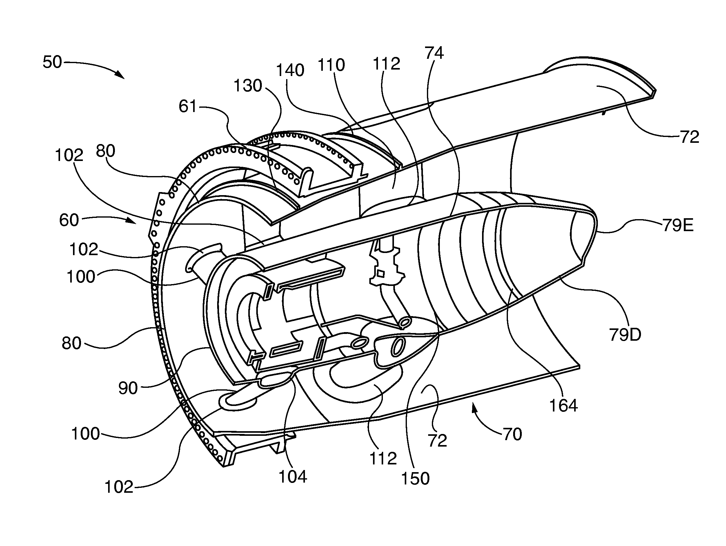
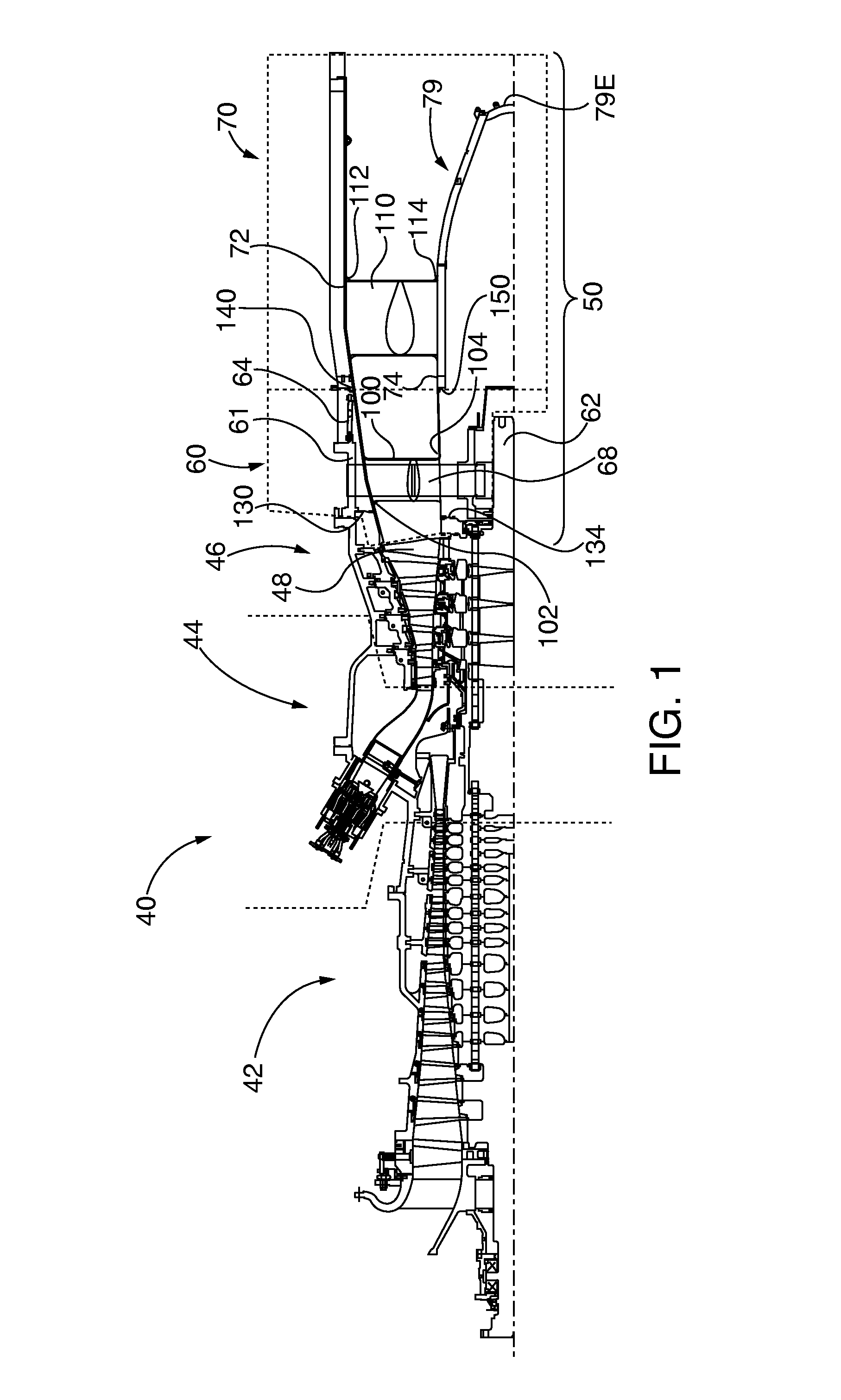
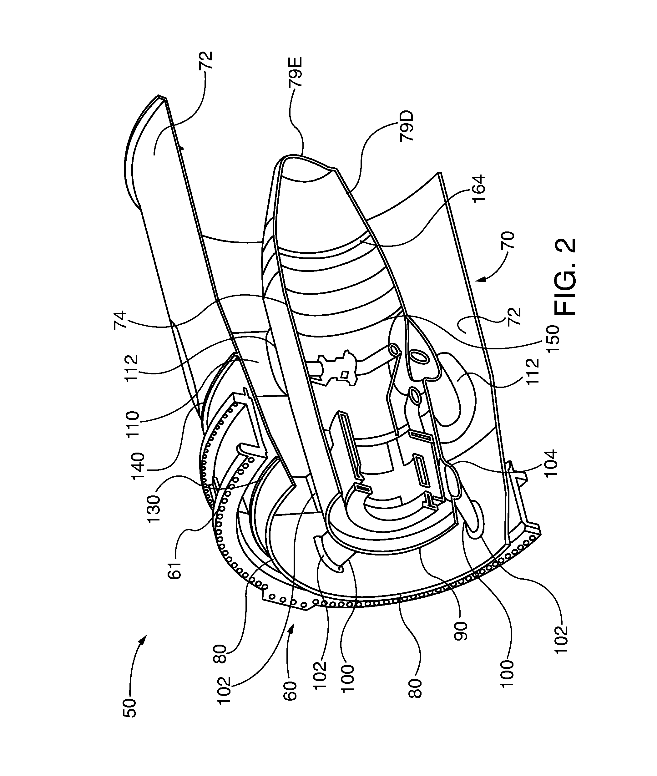
[0047]After considering the following description, those skilled in the art will clearly realize that the teachings of embodiments of the invention can be readily utilized in by an industrial gas turbine (IGT) drop-in single-piece exhaust system (SPEX) with modular construction comprising a turbine exhaust case (TEC) mated to a turbine exhaust manifold (TEM), which when combined form opposed inner and outer exhaust cases that define an exhaust flow path. The inner and outer exhaust cases are constructed of a series splined, compound curves and / or of cylindrical and frusto-conical sections that mimic splined curves. Other modular portions of the SPEX can be utilized jointly and severally as needed to enhance airflow characteristics, including by way of example: (i) a splined, compound curve tail cone assembly that may be fabricated from a plurality of frusto-conical sections that taper downstream to a reduced diameter; (ii) an area-ruled cross section axially aligned with one or more...


PUM


Abstract

An integrated single-piece exhaust system (SPEX) with modular construction that facilitates design changes for enhanced aerodynamics, structural integrity or serviceability. The SPEX defines splined or curved exhaust path surfaces, such as a series of cylindrical and frusto-conical sections that mimic curves. The constructed sections may include: (i) a tail cone assembly fabricated from conical sections that taper downstream to a reduced diameter; or (ii) an area-ruled cross section axially aligned with one or more rows of turbine struts; or both features. Modular inner and outer diameter inlet lips enhance transitional flow between the last row blades and the SPEX, as well as enhance structural integrity. Modular strut collars have large radius profiles between the SPEX annular inner diameter and outer diameter flow surfaces, for enhanced airflow and constant thickness walls for uniform heat transfer and thermal expansion. Scalloped mounting flanges enhance structural integrity and longevity.

Description

CROSS-REFERENCE TO RELATED APPLICATIONS[0001]The following family of five related co-pending United States utility patent applications is being filed concurrently on the same date, which are all incorporated by reference herein:[0002]“Industrial Gas Turbine Exhaust System With Splined Profile Tail Cone”, filed on ______, Ser. No. ______, file 2013P02367US.[0003]“Industrial Gas Turbine Exhaust System Diffuser Inlet Lip”, filed on ______, Ser. No. ______, file 2013P18971US.[0004]“Industrial Gas Turbine Exhaust System With Area Ruled Exhaust Path”, filed on ______, Ser. No. ______, file 2013P18972US.[0005]“Industrial Gas Turbine Exhaust System With Modular Struts and Collars”, filed on ______, Ser. No. ______, file 2013P18973US and[0006]“Modular Industrial Gas Turbine Exhaust System”, filed on ______, Ser. No. ______, file 2013P18974US.BACKGROUND OF THE INVENTION[0007]1. Field of the Invention[0008]Embodiments of the invention relate to industrial gas turbine exhaust systems, and more ...

Claims


Application Information

Patent Timeline
IPC IPC(8): F01D25/30
CPCF01D25/30F05D2250/15F01D5/143F01D9/041F01D11/001F01D25/162F01D25/243F02K1/80F02K1/82F02K1/78
Inventor SALUNKHE, ANIL L.OROSA, JOHN A.SHTEYMAN, YEVGENIYHAN, LIJUANDELISA, III, MATTHEW J.RIVEROS, DANIEL F.
Owner SIEMENS ENERGY INC
Why Eureka
Eureka Blog
Learn More