Expanding type clamp used on lathe and machining method thereof

A processing method and expansion technology, which are used in the expansion fixture and processing field of lathes, can solve the problems such as can not meet the processing of special parts with small diameter and thin wall, poor control of coaxiality, and low clamping force of fixtures. , to achieve the effect of uniform and reliable clamping force, simple structure and convenient operation.

Active Publication Date: 2013-08-21
JIANGSU XINGHE VALVE +1
View PDF5 Cites 19 Cited by
  • Summary
  • Abstract
  • Description
  • Claims
  • Application Information

AI Technical Summary

Problems solved by technology

[0002] When machining on a lathe, parts are usually clamped from the outside to the inside, but if there are thin-walled parts that require high machining accuracy and coaxiality, are conical in shape and have no cylindrical surface, and are not too long, when the parts When one end of the machine needs to be machined after the other end is processed, the clamping force of the universal fixture is low, easy to deform, and the coaxiality is not easy to control, which cannot meet the requirements
Although expansion chucks have appeared on the market, they cannot meet the processing of special parts with small diameters and thin walls.

Method used


Image

  • Expanding type clamp used on lathe and machining method thereof
  • Expanding type clamp used on lathe and machining method thereof
  • Expanding type clamp used on lathe and machining method thereof

Examples


Embodiment Construction

[0046] The present invention will be further described below in conjunction with the accompanying drawings and embodiments.

[0047] Option One:

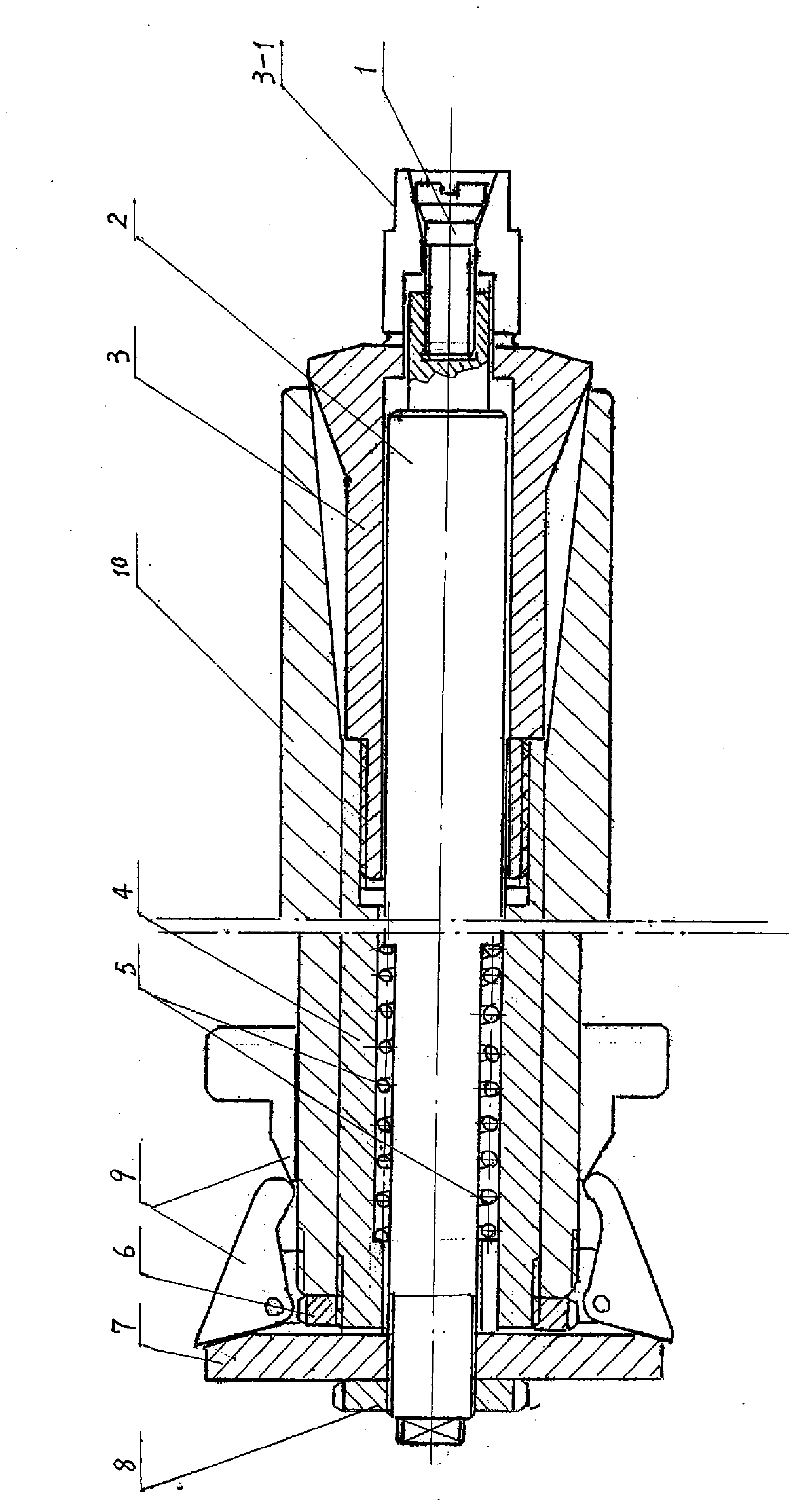
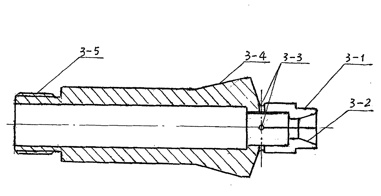
[0048] 1. An expansion fixture and a processing method on a lathe, in figure 1 Among them, it is composed of a shaft sleeve 4, a pull rod 2, a spring 5, an expansion chuck 3, an elastic screw 1, an adjusting nut 7, a nut 6, etc., and is characterized in that: the spring 5 and the pull rod 2 are respectively placed in the shaft sleeve 4, Thread the expansion chuck 3 into the shaft sleeve 4, and install the shaft sleeve 4 into the hole 10 of the lathe spindle, so that the expansion chuck neck 3-4 coincides with the inner taper hole end of the lathe spindle 10, and the other end of the shaft sleeve 4 is threaded Expose the tail end of the lathe spindle 10, screw in the nut 6 and tighten it. From the bell mouth 3-2 at the end of the expansion chuck 3, screw the elastic screw 1 into the internal thread at the end of the pull rod 2 and ...


PUM


Abstract

The invention discloses an expanding type clamp used on a lathe and a machining method thereof. A workpiece is usually clamped from outside to inside when being machined on the lathe. However, for a short thin-wall workpiece which has a cone-shaped outer surface, does not have a cylindrical surface and has high requirements for machining accuracy and coaxiality, when machining of one end of the workpiece is finished and the other end needs to be machined, a universal clamp can not meet the requirements due to the fact that the universal clamp is low in clamping force and prone to deformation. The expanding type clamp used on the lathe and the machining method thereof are suitable for being used in the situation that machining of one end of a short thin-wall workpiece, with a small inner diameter and a cone-shaped or angular outer surface and having high requirements for machining accuracy and coaxiality and free of a cylindrical surface, is finished and the other end needs to be machined. A hole of the machined workpiece is sleeved on an expanding type clamping head first, and then the circumference of the clamp expands outwards evenly in a clamping process to stretch the inner diameter of the workpiece to be machined to carry out lathe work. The clamp is loosened after the machining is finished, the expanding type clamping head contracts elastically, and then the machined workpiece is taken down easily.

Description

technical field [0001] The invention relates to the design and manufacture of a fixture for processing parts on a lathe. Usually, the fixture clamps the workpiece from the outside to the inside, but when some holes are centered and cannot be clamped externally, expansion fixtures are required for processing. Background technique [0002] When machining on a lathe, the parts are usually clamped from the outside to the inside, but if there are thin-walled parts that require high machining accuracy and coaxiality, external conical shape and no cylindrical surface, not too long, when the parts When one end of the machine needs to be machined after the other end is processed, the clamping force of the universal fixture is low, easy to deform, and the coaxiality is not easy to control, which cannot meet the requirements. Although expansion collets have appeared on the market, they cannot meet the processing of special parts with small apertures and thin walls. Contents of the i...

Claims


Application Information

Patent Timeline
Patent Type & Authority Applications(China)
IPC IPC(8): B23B31/40B23P15/00
Inventor 朱义芳
Owner JIANGSU XINGHE VALVE
Why Eureka
Try Eureka