Stiffening element and a method for manufacturing of a stiffening element

a technology of stiffening element and manufacturing method, which is applied in the field of aircraft industry, can solve the problems of time-consuming and labor-intensive to form aircraft ribs of composite materials, difficult to provide fibre materials, and manual work for application of prepreg materials, etc., and achieve the effect of increasing the stiffness of the stiffening elemen

Inactive Publication Date: 2007-06-21
SAAB AB
View PDF0 Cites 18 Cited by
  • Summary
  • Abstract
  • Description
  • Claims
  • Application Information

AI Technical Summary

Benefits of technology

[0006] Thereby an essentially flat blank of composite material layers having a rectangular continuous extension can be used in a cost effective manner. The production of composite material having a curvature following the curvature of a single curved shell surface is thus simplified, that is, composite material in for example aircraft ribs. Since all composite material (such as plastic) is used in the process and since the fibre orientation optimally can be utilized weight is saved. The plastic material being curable, such as thermosetting resin. Each plastic layer preferably comprises reinforcement elements, for example carbon / glass or aramid fibres, that extend substantially continuously in one direction in the plane of each layer. Different layers have fibres aligned in different directions. A complementary relationship between the radius of curvature of the outer flange surface (fixation flange) and the reduction of length in the main direction of the first elongated edge of the blank is used. By means of the rounded conical bulge, the web will bend.
[0010] Thereby the stiffening element can be finished (exclusively for eventual fastening arrangement for attachment of the stiffening element to the single curved shell surface) in a short time and in a labour saving manner, directly in the forming tool.
[0014] Thereby the manufacturing of stiffening elements of composite material can be cost-effective since the blank has a rectangular form. The manufacture is time-saving and the ATML-machine can be re-programmed for different types of blanks earmarked for a certain stiffening element dedicated for a certain aircraft type. Prepreg tapes including fibres that extend continuously within the tape are to be applied in the longitudinal direction of the blank. Perpendicular and diagonally to the longitudinal direction of the blank, sections of prepreg tape will be applied rapidly and accurately resulting in fibre orientation in a direction transverse and diagonally to the longitudinal direction of the blank. Other layers may have fibres aligned in different directions.
[0019] In such way the stiffening element will have a considerable strength and at the same time a low weight, which is desirable for aircraft assemblies. The reinforcement fibres extend continuously unbroken in the direction of curvature for each layer. The fibres located in the web follow the bulge curvature of the web and the fibres located in the outer flange follow the curvature of the flange. Since all positions of the stiffening element can have fibres with optimized directions for strength reasons, the weight of the stiffening element can be minimized. Furthermore, the bulge curvature of the web stiffens the stiffening element, resulting in a strength improvement of the same without the need of any stiffening bars, or thicker material of the web etc.
[0020] Preferably is a free flange provided at the web for stiffening the element.
[0023] Thereby the strength of the stiffening element is increased, since large bending loads are to be carried by the inner flange.

Problems solved by technology

It is today time-consuming to form an aircraft rib of composite material.
Manual work for application of prepreg material is required since it is difficult to provide that the fibre material follows the curvature.
Especially C-shaped aircraft ribs of composite material are difficult to manufacture since the fibre material tend to not follow the curvature.

Method used


Image

  • Stiffening element and a method for manufacturing of a stiffening element
  • Stiffening element and a method for manufacturing of a stiffening element
  • Stiffening element and a method for manufacturing of a stiffening element

Examples


first embodiment

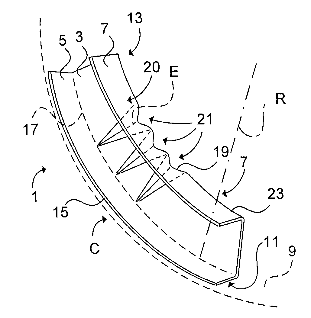
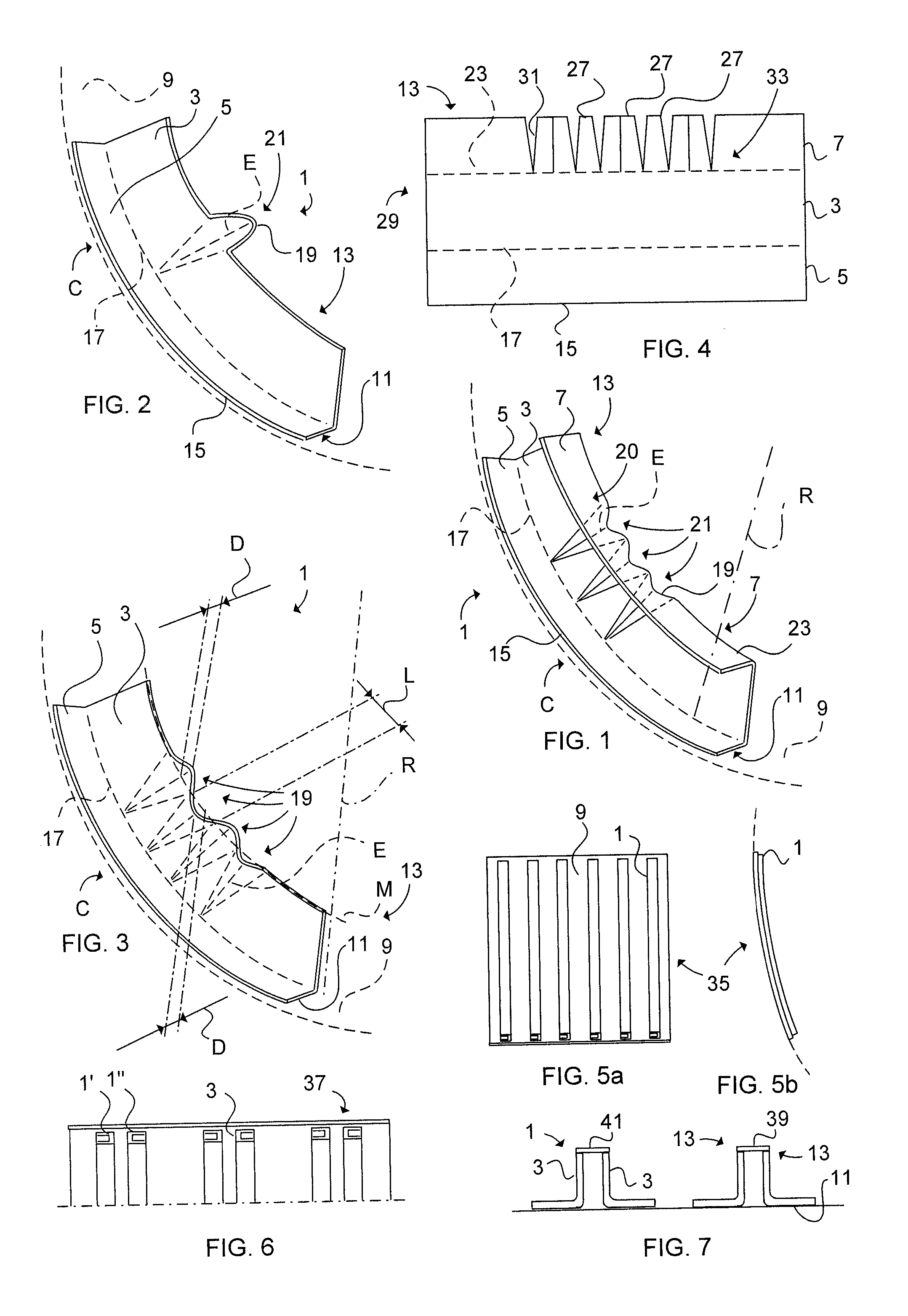
[0036] Referring to FIG. 1, a stiffening element 1 of composite material, such as thermosetting resin, comprises a web 3 and an outer 5 and inner 7 flange according to a The outer 5 flange (fixation flange) is provided for attachment to a single curved shell surface 9. The outer surface 11 of the outer flange 5 has a radius of curvature R corresponding with the radius of the single curved shell surface 9 curvature C. The inner flange 7 (free flange) includes a first elongated edge 13 which is shorter than a second elongated edge 15 of the outer flange 5. A first folding line 17 is formed between the outer flange 5 and the web 3. The web 3 comprises rounded conical bulges 19, each bulge 19 tapering from a base portion 21 of the bulge 19 essentially merging with a second folding line 23 of the inner flange 7 and the web 3. Each bulge 19 tapers in a direction towards the first folding line 17 and terminates with an apex 25 essentially merging with the first folding line 17. The bulge ...

second embodiment

[0038] Referring to FIG. 2 a stiffening element 1 comprises a web 3 and an outer flange 5 according to a The outer flange 5 (fixation flange) is formed for suitably attachment to a double curved shell surface 9. Between the web 3 and the outer flange 5 is a first folding line 17 formed. A singular bulge 19 is formed in the web 3. The reduction of length of the first elongated edge 13 of the web 3 by means of the bulge 19 provides a bent outer flange 5, still maintaining the outer flange 5 with an even surface, which is desirably.

[0039] Referring to FIG. 3 a stiffening element 1 includes four bulges 19, two of which are defined as furrows and two are defined as ridges. Respective bulge 19 has an arcuate shape (wave shaped furrows and ridges) in cross section tapering towards the first folding line 17. A complementary relationship between the radius R of curvature of the outer flange surface 11 and a reduction of length in the main direction M (centre axis) of the first elongated edg...


PUM

PropertyMeasurementUnit
radius of curvatureaaaaaaaaaa
curvatureaaaaaaaaaa
timeaaaaaaaaaa

Abstract

The present invention relates to a stiffening element (1) and a method for manufacturing of a stiffening element (1) of composite material, which stiffening element (1) is provided for attachment to a curved shell surface (9). A substantial flat blank (29) of composite material comprising a first (13) and a second (15) essentially parallel elongated edge is provided for forming in the web (3) of the stiffening element (1) at least one rounded bulge (19) having a conical form tapering from the first edge (13) to a first folding line (17). Thereby is achieved a curved flange (5), which first folding line (17) essentially merges with an apex of the rounded bulge (19).

Description

FIELD OF THE INVENTION [0001] The present invention relates to a method for manufacturing of a stiffening element of composite material according to the pre-characterising part of claim 1, and to a stiffening element of composite material according to the pre-characterising part of claim 6. The present invention relates, but not limited, to aircraft industry. BACKGROUND OF THE INVENTION [0002] Methods of manufacture of composite materials using “prepreg” material (layer of fibre material previously impregnated with resin) exist today. When manufacture of stiffening elements, such as aircraft ribs, frames etc., the composite material may have a curvature following a single curved or a double curved shell surface of a fuselage. It is today time-consuming to form an aircraft rib of composite material. Manual work for application of prepreg material is required since it is difficult to provide that the fibre material follows the curvature. Especially C-shaped aircraft ribs of composite ...

Claims


Application Information

Patent Timeline
Patent Type & Authority Applications(United States)
IPC IPC(8): B29C45/14B29D99/00
CPCB29C70/345B29C70/462B29D99/0014
Inventor KROGAGER, MAXRUDQVIST, CLAESWEIDMANN, BJORNPETERSSON, MIKAEL
Owner SAAB AB
Why Eureka
Try Eureka