Reflectometry system with compensation for specimen holder topography and with lock-rejection of system noise
Inactive Publication Date: 2006-04-18
EY LABORATORIES INC
View PDF93 Cites 20 Cited by
Summary
Abstract
Description
Claims
Application Information
AI Technical Summary
This helps you quickly interpret patents by identifying the three key elements:
Problems solved by technology
Method used
Benefits of technology
Benefits of technology
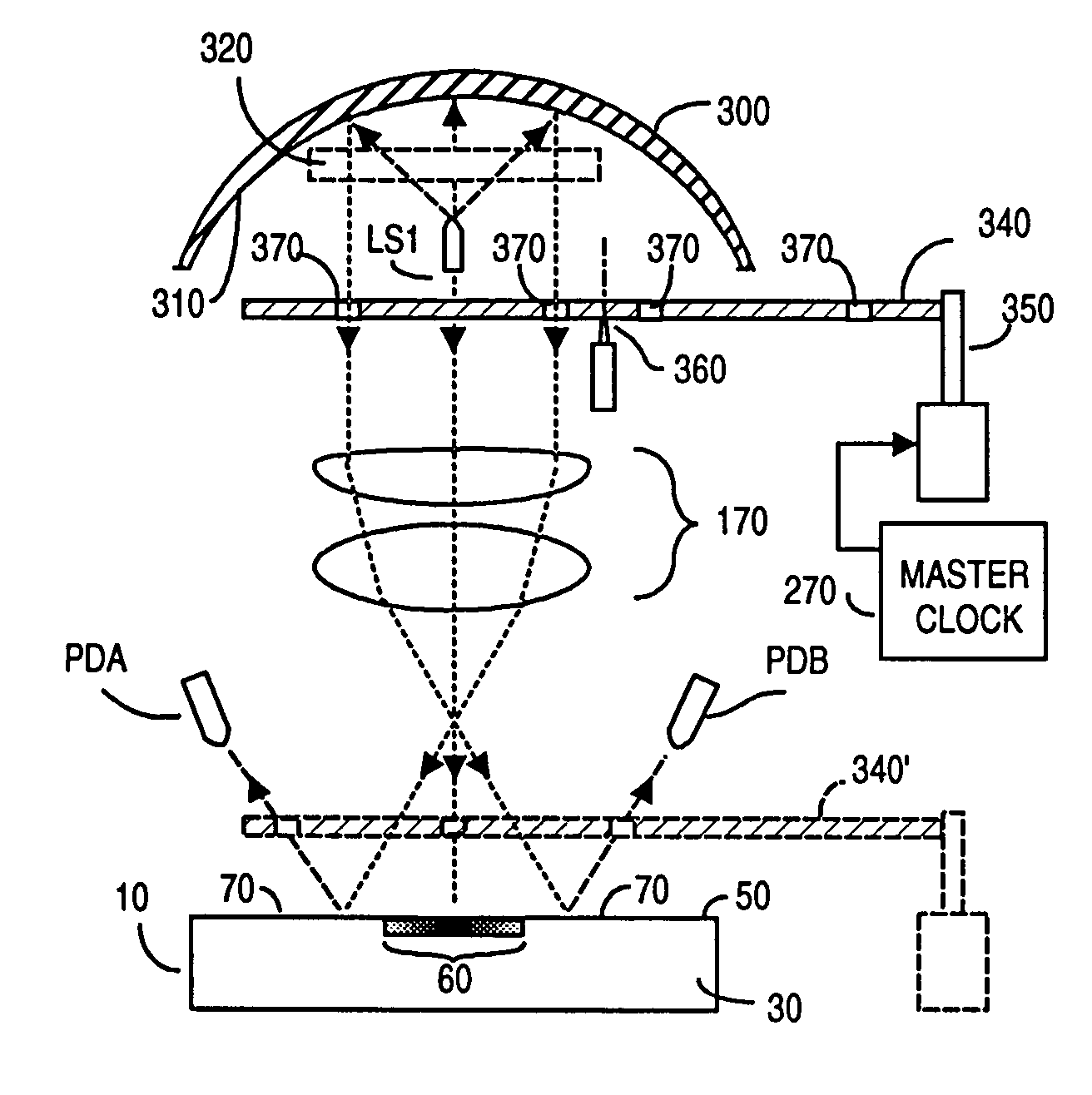
[0022]The invention provides two sub-systems: a sub-system that substantially reduces skew error due to uneven device topography, and a phase lock-in amplifier sub-system to enhance detected signal/noise by measuring signal voltage without producing noise.
[0023]In the first sub-system, the present invention recognizes that poor topography associated with commonly used membranes can contribute an uncertainty error of at least ±1% in reflected light intensity readings. This error, which is approximately sinusoidal, is substantially cancelled by monitoring reflected light intensity using two PDs spaced-apart from each other 180° azimuthally. Should a membrane be fabricated from cross-linked cardboard, then the two PDs are spaced-apart from each other 90° azimuthally. So disposing a pair of PDs a chosen multiple of 90° azimuthally apart, and averaging their output signals can improve accuracy ±1% or more.
[0024]In the second sub-system, the averaged PD output signal is
Problems solved by technology
But often tests do not produce readily ascertainable “yes” or “no” results that are unambiguously apparent, even for a laboratory technician who is experienced in performing the tests and reading the results.
As a further complication, densitometers used in such tests cannot measure more than a single point in a color band.
Thus, while densitometry can produce automated results, the results may vary greatly and can be highly inaccurate.
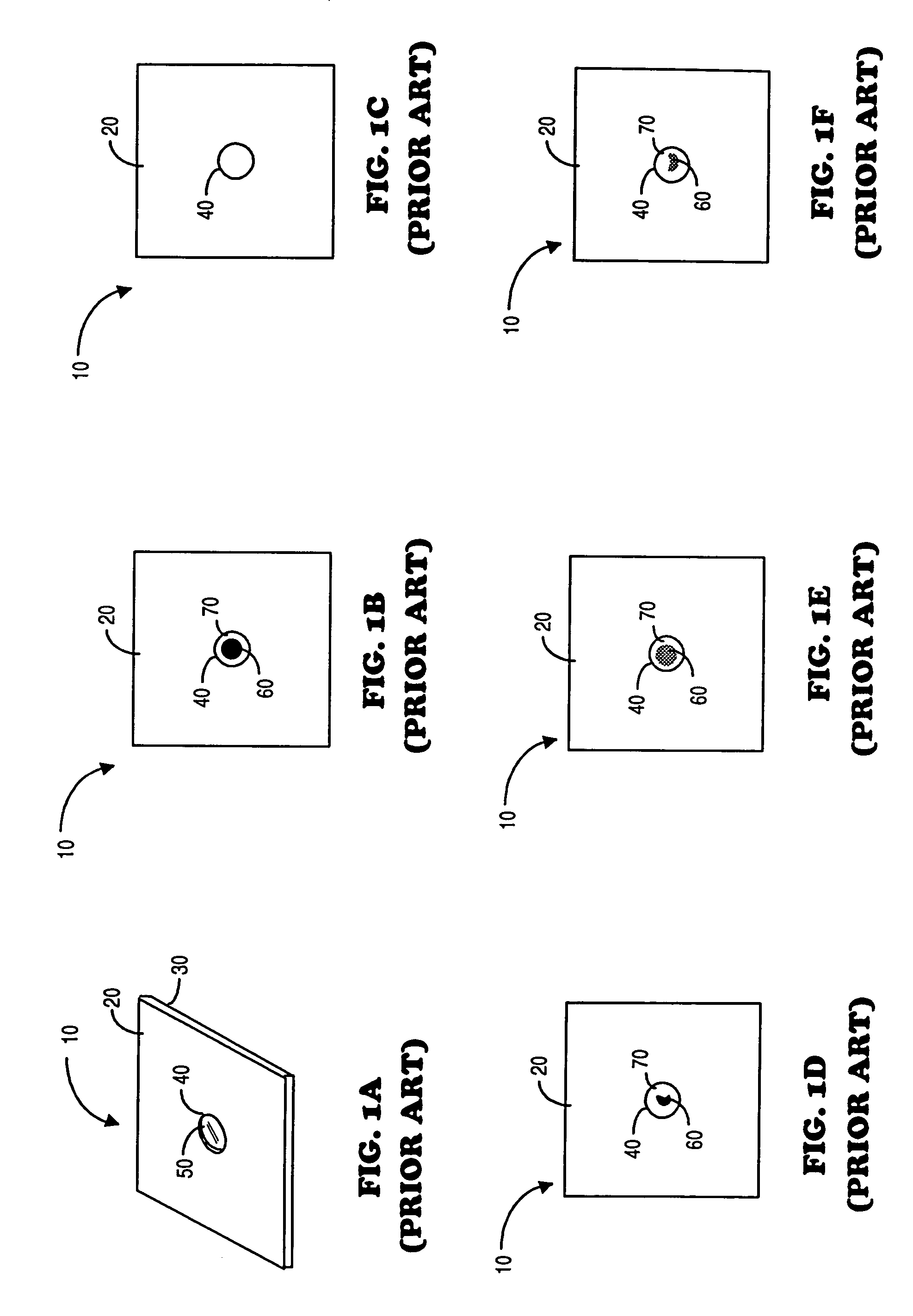
In FIG. 1D, a dark spot is present, but as may often be the case, the spot is not uniform in shape and may be smaller in size than anticipated.
It can be rather difficult to accurately discern reflectivity of spot 60 relative to the surrounding region 70.
Even a trained human eye cannot resolve changes in reflectivity as small as a few percent.
The human eye is also a poor reflectometry instrument when one must examine many devices 10 within a given time.
Fatigue, subjective differences in observation, and errors can result in different analysis results, even when reflectivity changes are large enough to permit differentiation with the eye.
But unless the device is inserted into the reflectometer in an aligned manner, light from the receptor spot area may not be accurately measured.
Indeed, f
Method used
Image
Click on the blue label to locate the original text in one second.
Reading with bidirectional positioning of images and text.
Examples
Embodiment Construction
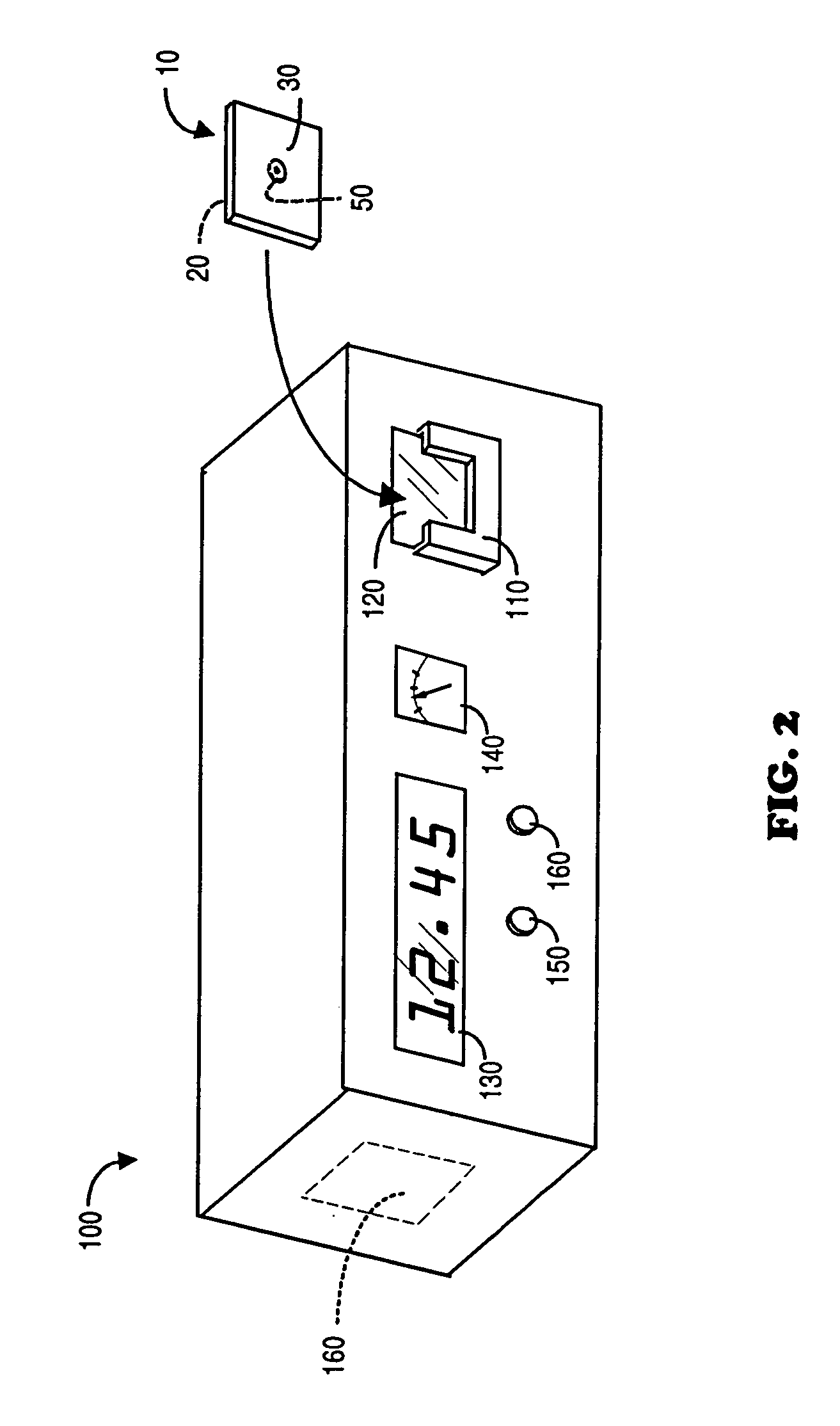
[0046]FIG. 2 is a perspective view of the present invention, a reflectometer system 100 with compensation for specimen holder topography and with lock-rejection of system noise. The housing for system 100 includes a device holder 110 that is mounted adjacent a window 120 that is substantially transparent to light generated within system 100. Holder 110 is sized to retain a device 10 such as described earlier herein. Device 10 is inserted into holder 110 with the chemically dyed spot facing window 120. (As used herein, the term dyed spot refers generically to a characteristic change in region 60, for example, any change in contrast, in color, color or optical density, without limitation.)
[0047]Thus, surface 20 of device 10 faces system 100, and opposite surface 30 faces away from system 10. In a preferred embodiment, system 100 includes a visual readout device, preferably a digital readout 130 and / or an analog readout device 140. Of course readout device 130 and / or 140 could be repla...
PUM
Abstract
A self-contained system uses light reflectivity to examine intensity of a dyed spot on a device membrane surrounded by background area to discern information about the specimen that produced the spot. In a preferred embodiment, a master clock alternatively drives one LED focussed upon the spot center, and then drives two LEDS focused on the background area. Light reflected from the spot and background is detected by preferably two photodetectors (“PDs”) spaced-apart a multiple of 90° azimuthal.
Description
RELATIONSHIP TO OTHER PENDING APPLICATIONS[0001]This is a continuation of application Ser. No. 09 / 610,667 filed Jul. 5, 2000 entitled REFLECTOMETRY SYSTEM WITH COMPENSATION FOR SPECIMEN HOLDER TOPOGRAPHY AND WITH LOCK-REJECTION OF SYSTEM NOISE which will issue as U.S. Pat. No. 6,584,217 on Jun. 24, 2003, which was a continuation of application Ser. No. 09 / 021,419, filed on Feb. 10, 1998, now abandoned which was a continuation-in-part from application Ser. No. 08 / 465,089 filed Jun. 5, 1995, entitled OPTICAL SPECIMEN ANALYSIS SYSTEM AND METHOD, which issued as U.S. Pat. No. 5,717,778 on Feb. 10, 1998, and from application Ser. No. 08 / 995,590 entitled OPTICAL SPECIMEN ANALYSIS SYSTEM AND METHOD, filed on Dec. 22, 1997, a continuation of said Ser. No. 08 / 465,089. Applicants incorporate each said application herein by reference.FIELD OF THE INVENTION[0002]The invention relates to reflectometry systems in general, and more particularly to reflectometry systems and methods used to analyze ...
Claims
Application Information
Patent Timeline
Application Date:The date an application was filed.
Publication Date:The date a patent or application was officially published.
First Publication Date:The earliest publication date of a patent with the same application number.
Issue Date:Publication date of the patent grant document.
PCT Entry Date:The Entry date of PCT National Phase.
Estimated Expiry Date:The statutory expiry date of a patent right according to the Patent Law, and it is the longest term of protection that the patent right can achieve without the termination of the patent right due to other reasons(Term extension factor has been taken into account ).
Invalid Date:Actual expiry date is based on effective date or publication date of legal transaction data of invalid patent.

