
Method and apparatus for end to end forwarding architecture

Inactive Publication Date: 2006-04-25
RPX CORP +1
View PDF6 Cites 197 Cited by
  • Summary
  • Abstract
  • Description
  • Claims
  • Application Information

AI Technical Summary

Problems solved by technology

This requires more hardware while requiring additional time for sending and receiving data and data management commands.

Method used


Image

  • Method and apparatus for end to end forwarding architecture
  • Method and apparatus for end to end forwarding architecture
  • Method and apparatus for end to end forwarding architecture

Examples


Embodiment Construction

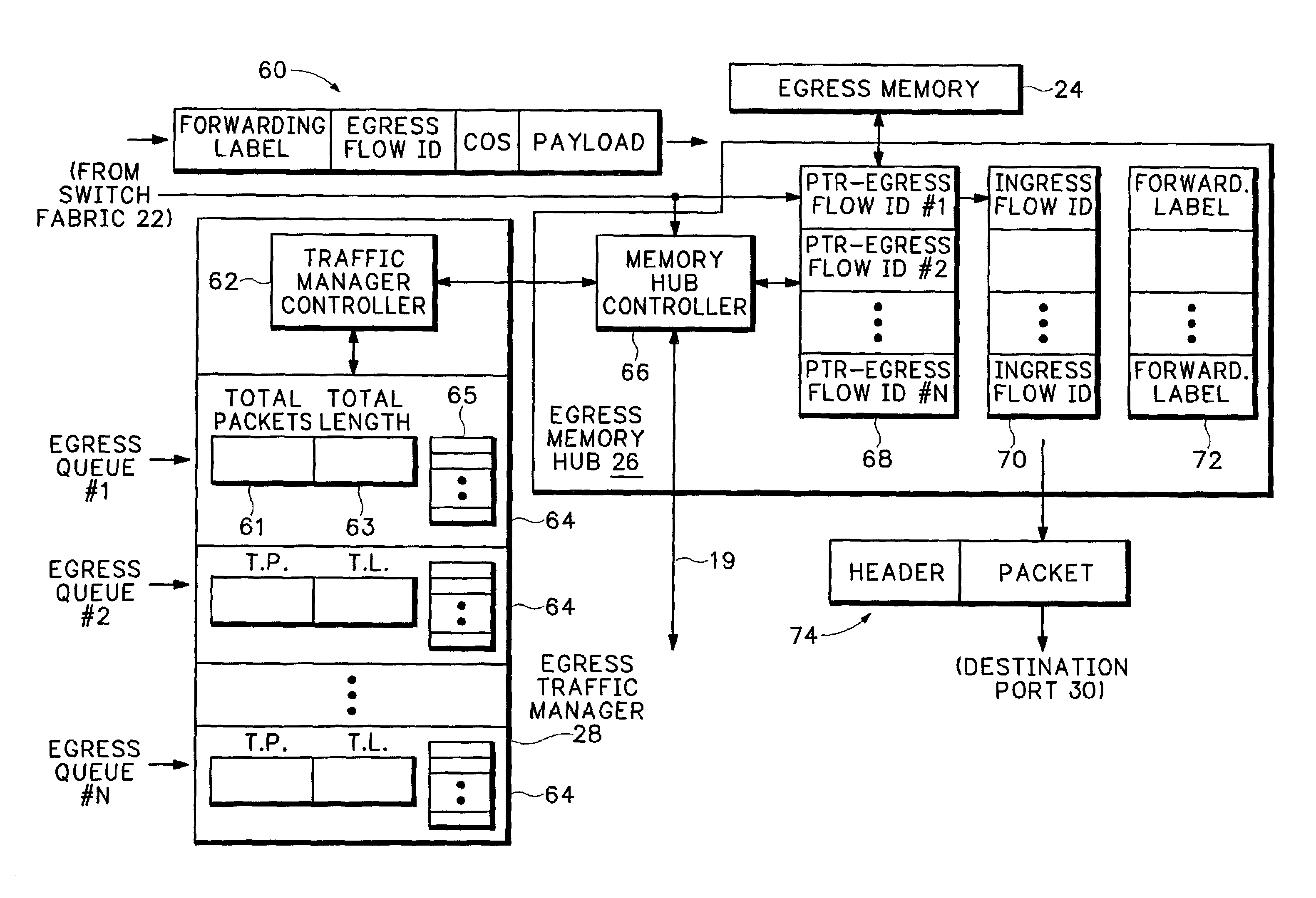
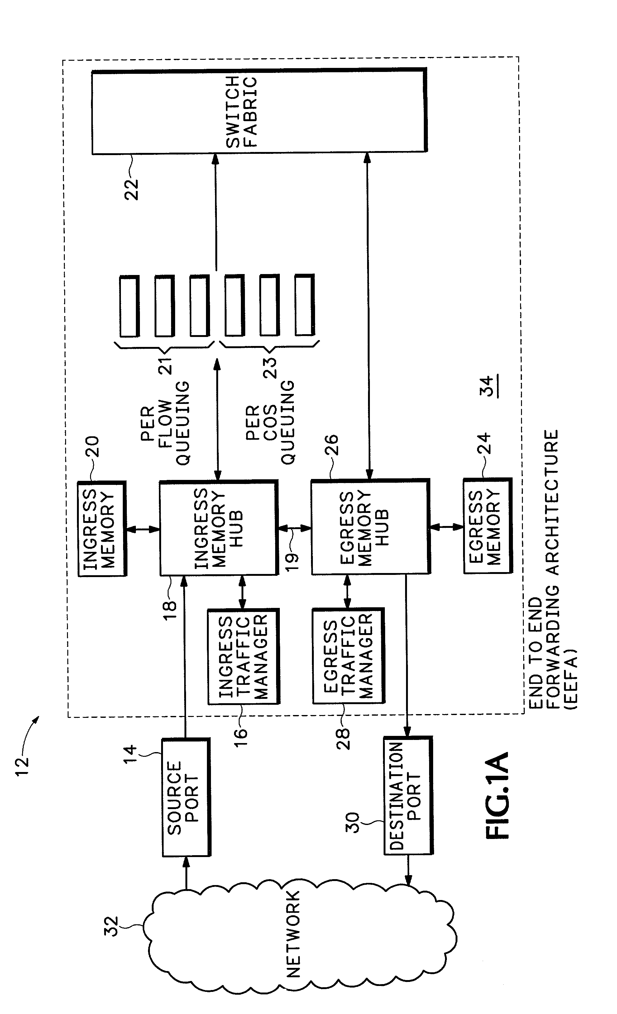
[0015]FIG. 1A shows a network processing device 12, such as may be used with concentrators, network gateways, Internet backbone routers, switches, etc. One of multiple source ports 14 receives packets from a network 32, such as a Local Area Network (LAN), Metropolitan Area Network (MAN) or Wide Area Network (WAN). The source port 14 assigns an ingress flow Id for a stream of packets. The ingress flow Id is inserted into a field in the packet headers. A flow is defined as a packet stream with similar bandwidth / Quality of Service or other similar packet processing requirements.

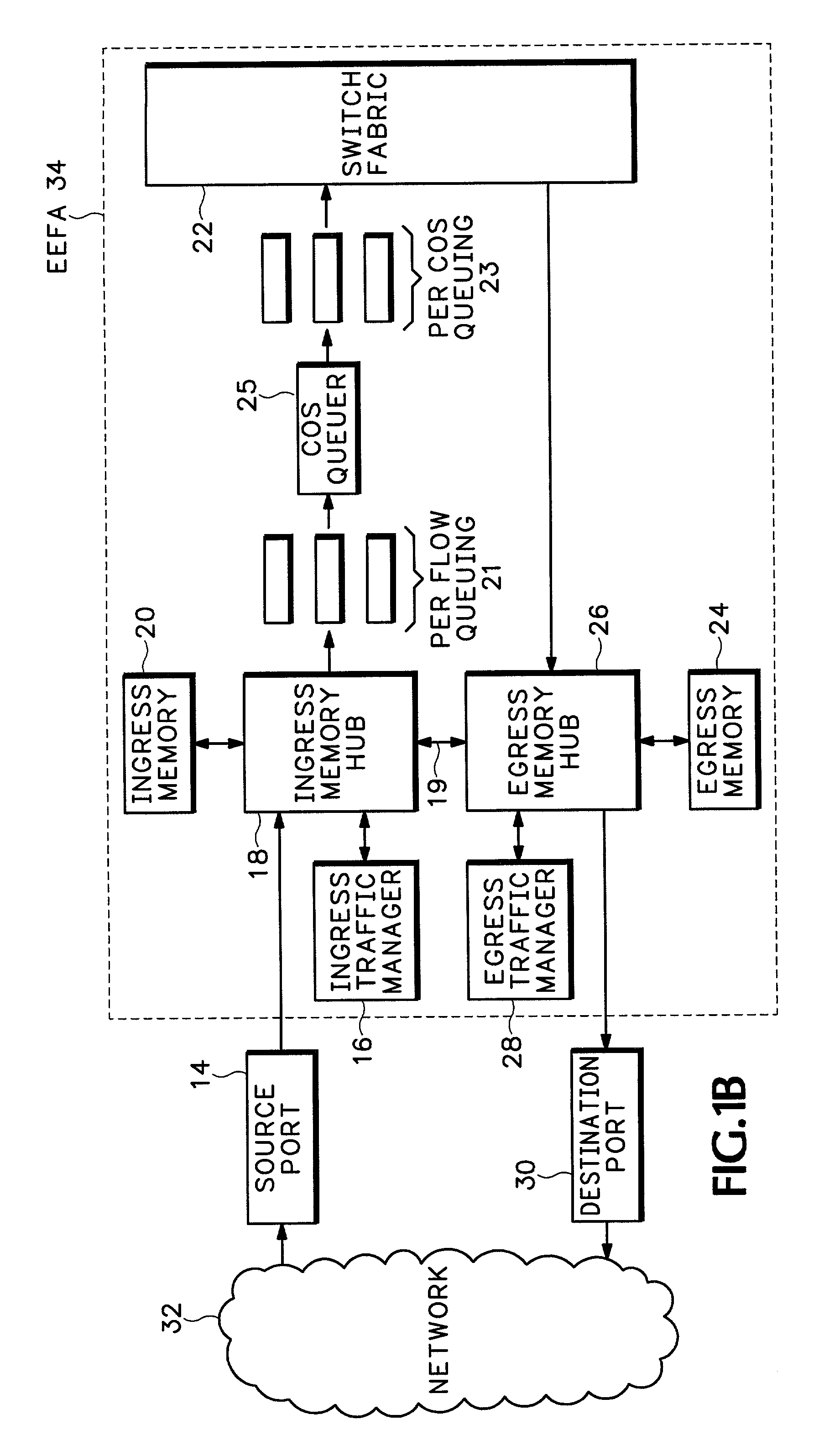
[0016]A switching architecture 34 includes ingress traffic manager 16, ingress memory hub 18, ingress memory 20, egress traffic manager 28, egress memory hub 26, egress memory 24, and switch fabric 22. The ingress memory hub 18 receives packets from the source port 14 through a first interface and stores the packets in ingress memory 20 according to the ingress flow Id in the packet header.

[0017]The ingress memo...


PUM


Abstract

An end to end forwarding architecture includes a memory hub having a first ingress interface for receiving packets from a source port. The packets have associated ingress flow identifiers. A second ingress interface outputs the packets to a switch fabric. An ingress controller manages how the packets are queued and output to the switch fabric. The same memory hub can be used for both per flow queuing and per Class of Service (CoS) queuing. A similar structure is used on the egress side of the switch fabric. The end to end forwarding architecture separates per flow traffic scheduling operations performed in a traffic manager from the per flow packet storage operations performed by the memory hub.

Description

BACKGROUND[0001]Current network processing architectures, such as used with network routers and network switches, include multiple line cards that receive packets from different input ports. On the ingress side of a switch fabric, a traffic manager receives the packets and queues the packets for sending to the switch fabric based on some quality of service criteria. The packets are queued by the traffic manager for outputting to a backplane interface that then forwards the packets to the switch fabric. The backplane interface provides an interface between the traffic manager and the switch fabric that queues the ingress flows according to their identified destination ports.[0002]The switch fabric establishes paths for forwarding the packets to output ports according to destination information attached to the packet headers. On the egress side of the switch fabric, the traffic manager processes the packets on a per flow basis from the different line cards sending packets over the swi...

Claims


Application Information

Patent Timeline
IPC IPC(8): H04L12/28
CPCH04L45/60H04L47/2441H04L49/254H04L49/201H04L49/3027H04L49/3018H04L49/205
Inventor MITTAL, MILLINDSHANKAR, LAXMAN
Owner RPX CORP
Learn More