

Flash control mechanism
- Summary
- Abstract
- Description
- Claims
- Application Information
AI Technical Summary
Benefits of technology
Problems solved by technology
Method used
Image

Examples
Embodiment Construction
[0061]The present invention will now be described with reference to an embodiment shown in the drawings.
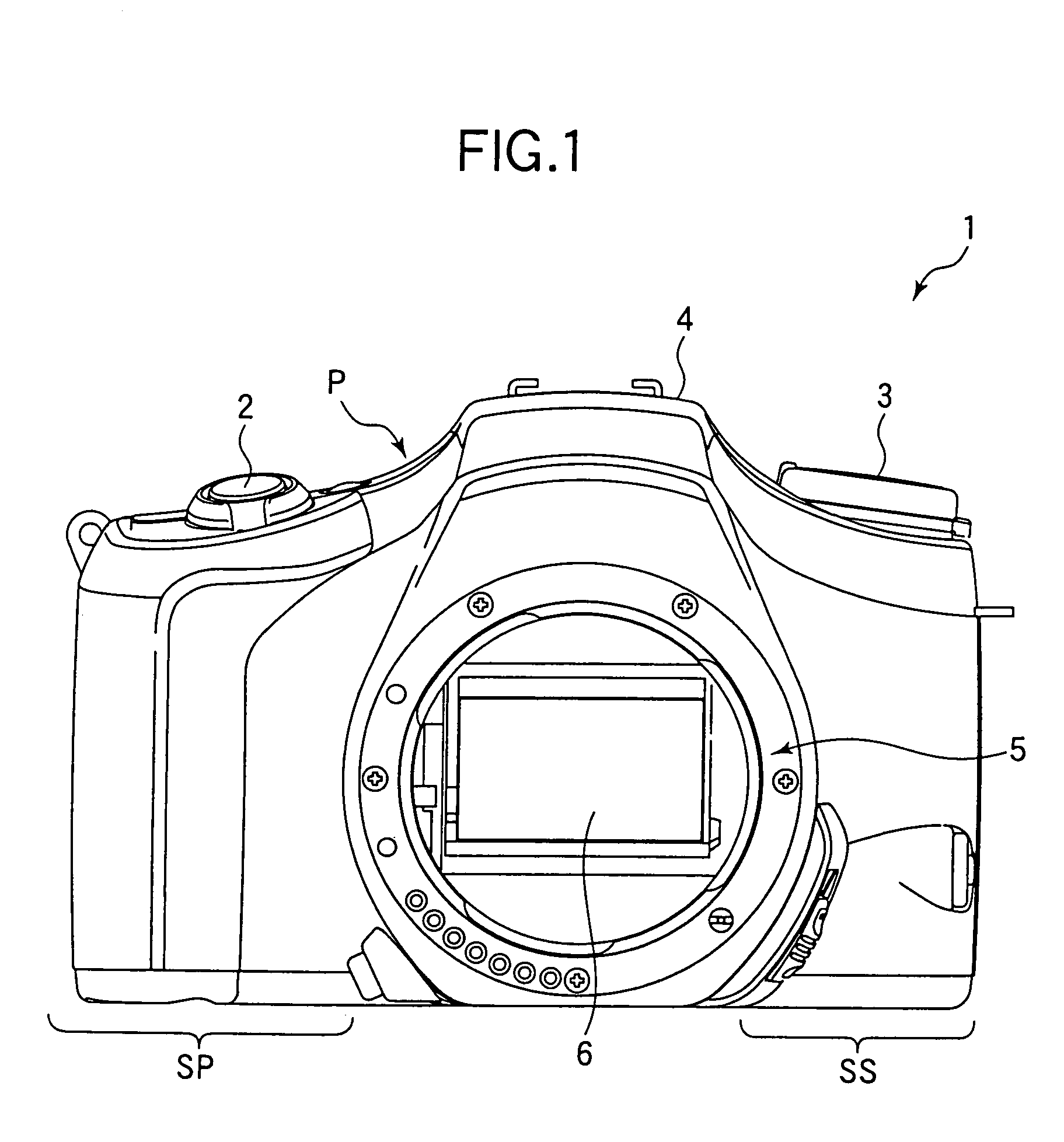
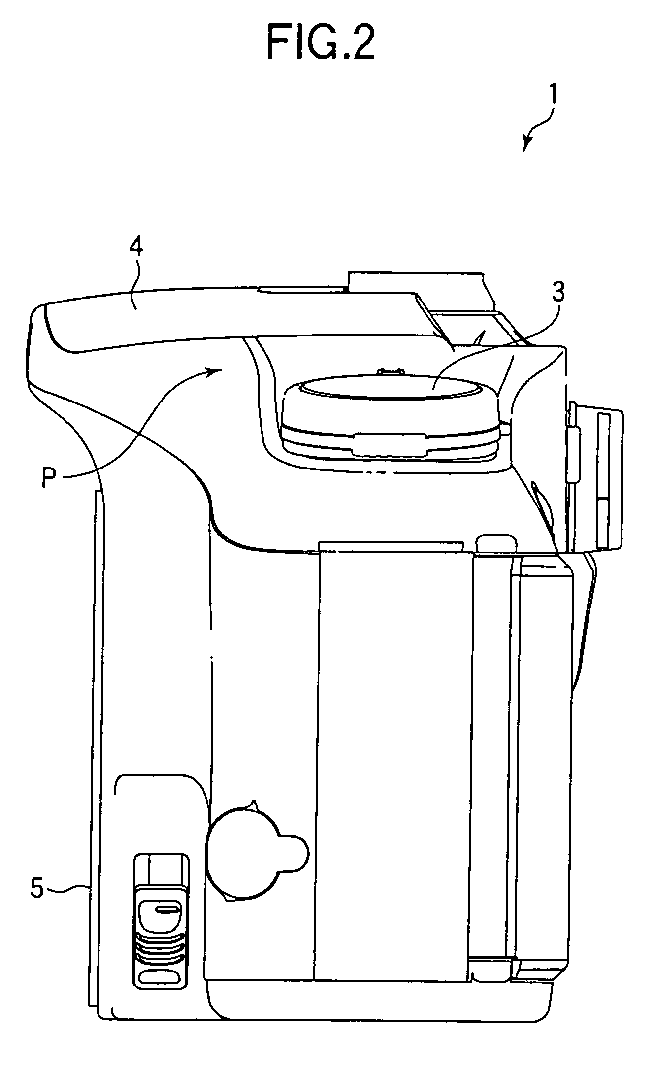
[0062]FIG. 1 is a front view of a camera body 1 of a single lens reflex camera to which an embodiment according to the present invention is applied. FIG. 2 is a side view of the camera body 1, viewed from the right side of FIG. 1.
[0063]An upper casing plate P is placed on the upper side of the camera body 1. A release button 2 is provided on the plate P, being positioned at the left side in FIG. 1. A setting dial 3 for setting various modes is provided on the plate P, being position at the right side in FIG. 1. A flash case 4 is positioned at the center of the plate P. A flash (not shown) is built in the flash case 4, being positioned at the front side end of the camera body 1. The flash case 4 is rotatably supported by a shaft which is provided at the back side end of the camera body 1. When the flash is not used, the flash case 4 is held at a storage position as shown in FIGS. 1...
PUM
 Abstract
Description
Claims
Application Information