

Developing apparatus having developer carrying screw with a plurality of inclination angles
a technology of developer and carrying screw, which is applied in the direction of electrographic process apparatus, instruments, optics, etc., can solve the problems of extreme difficulty in preventing the pitch of the screw completely uneven, and the conventional construction, so as to reduce the density of the imag
- Summary
- Abstract
- Description
- Claims
- Application Information
AI Technical Summary
Benefits of technology
Problems solved by technology
Method used
Image

Examples
first embodiment
(First Embodiment)
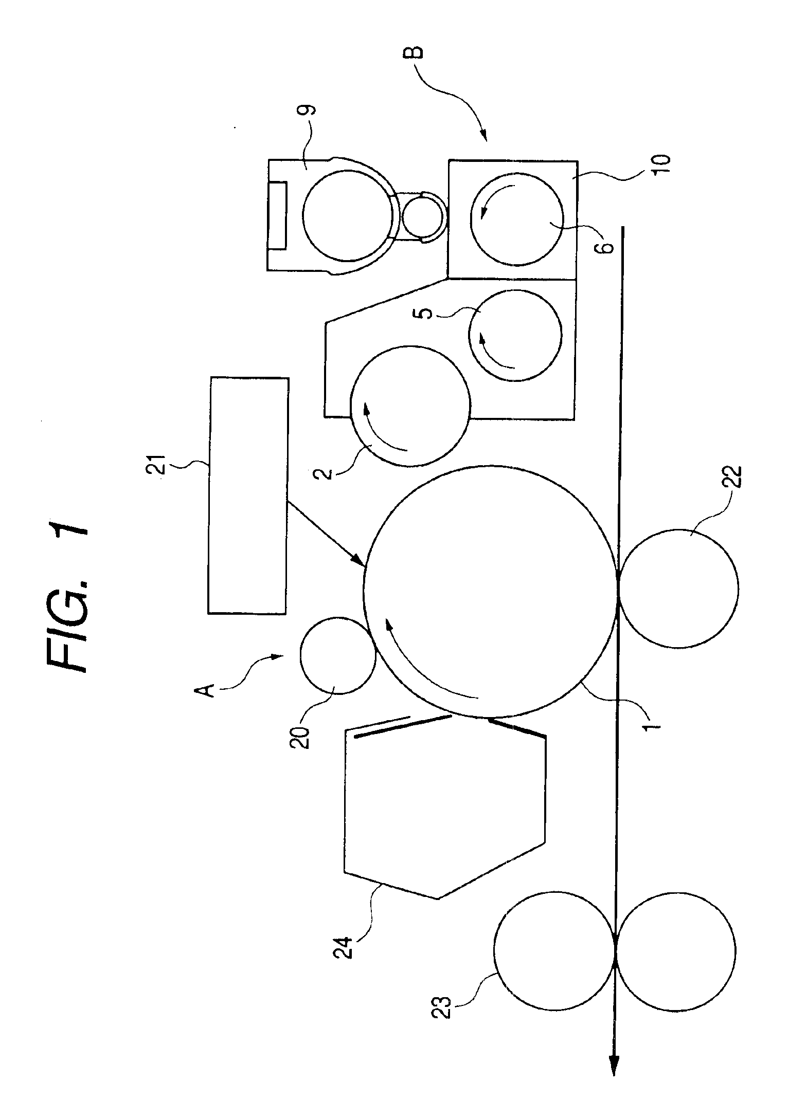
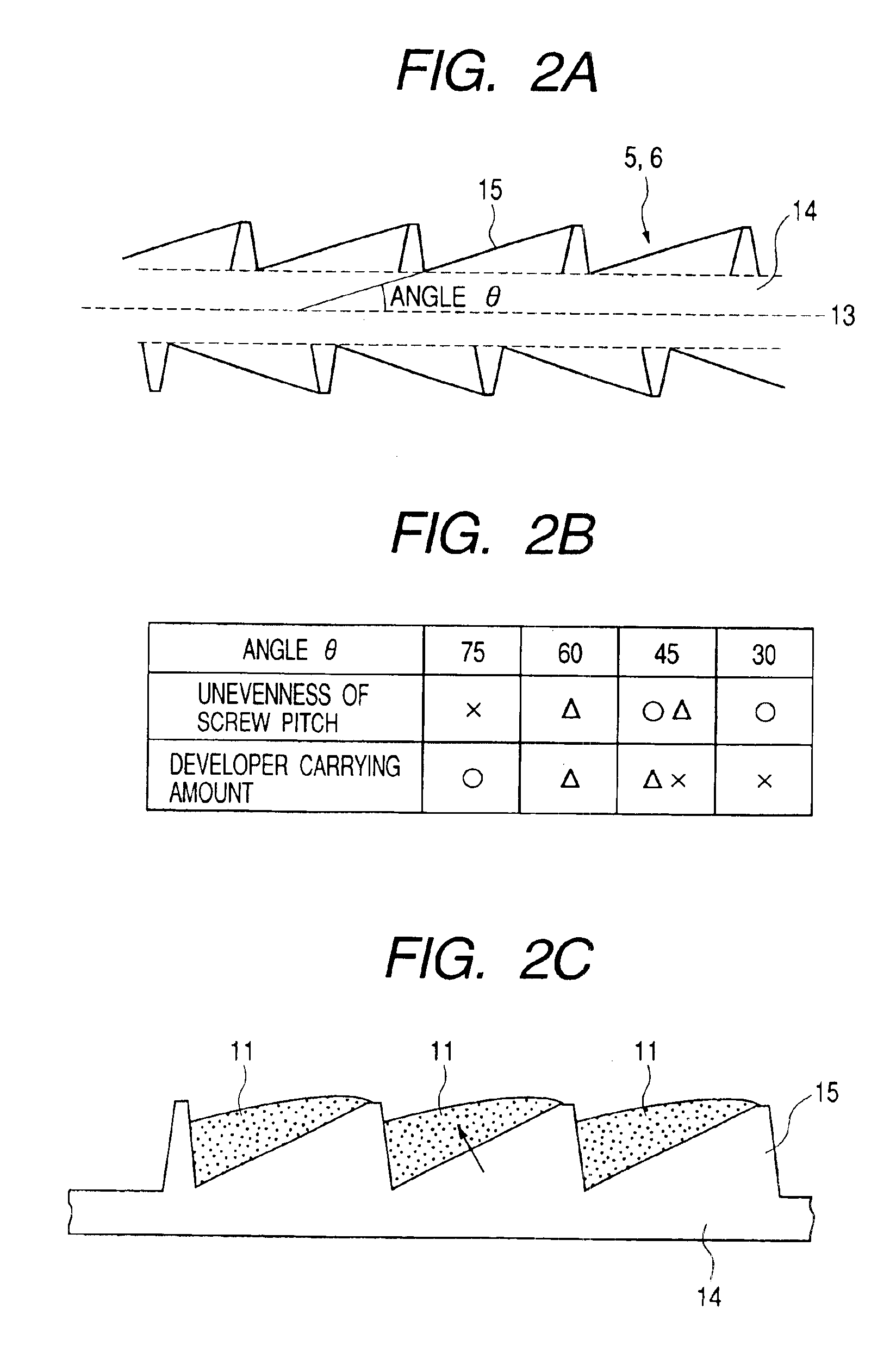
[0043]Next, an image forming apparatus including a developing apparatus according to a first embodiment of the present invention will be explained with reference to FIG. 1, FIGS. 2A, 2B and 2C. FIG. 1 is a schematic sectional view of an entire image forming apparatus, FIGS. 2A, 2B and 2C show a screw for carrying a developer, FIG. 2A is a sectional view cut by a plane passing through a rotation centerline of the screw, FIG. 2B is a table showing results of performing a developer carrying experiment by changing a blade angle, and FIG. 2C is an explanatory view of a state of the developer carried by the screw.
(Entire Construction of the Image Forming Apparatus)
[0044]First, the entire construction of an image forming apparatus A will be briefly explained with reference to FIG. 1. In FIG. 1, reference numeral 1 denotes a rotatable photosensitive member drum which is a latent image bearer, around which, an electrifier 20 for electrifying a surface of the photosensitive ...
second embodiment
(Second Embodiment)
[0056]In the aforementioned first embodiment, the carrying surface facing in the developer carrying direction of the blade of the screw is constructed by a single plane, but in this embodiment, the blade of the screw has “a plurality of carrying surfaces facing in a developer carrying direction and differing in inclination angles with respect to a shaft of a screw”. The explanation will be made with reference to FIGS. 3A, 3B and 3C, to FIGS. 5A and 5B.
[0057]FIGS. 3A, 3B and 3C show a screw of a developing apparatus according to a second embodiment, FIG. 3A is an outline view of the screw, FIG. 3B is a sectional view cut by a plane passing through a rotation centerline of the screw, and FIG. 3C is a table showing results of performing a developer carrying experiment by changing a blade angle. FIG. 4A is an explanatory view of a state of a developer carried by the screw, and FIG. 4B is a sectional view for explaining relationship of a distance (height) H1 from a sur...
third embodiment
(Third Embodiment)
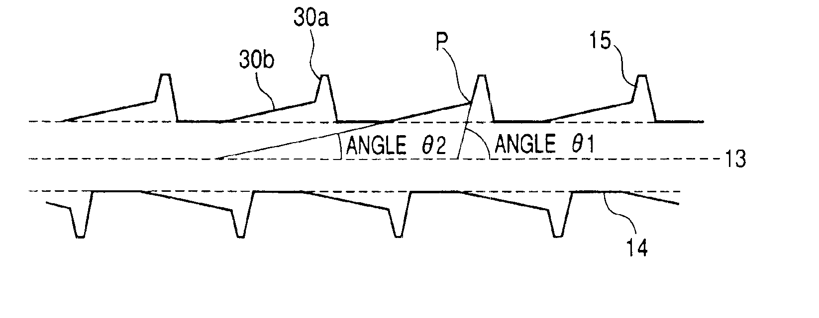
[0071]Next, a screw used in a developing apparatus of a third embodiment will be explained. FIG. 9 and FIG. 10 are sectional views each cut by a plane passing through a rotation centerline of the screw of this embodiment, and are the drawings each for explaining angles of the blades and length constituting the blades. A carrying direction of a developer in the drawings is leftward.
[0072]The construction of this embodiment is characterized by additionally providing a bulk-increasing spiral blade (a second blade) 16 as a bulk-increasing blade portion just behind the carrying spiral blade 15 (upstream side in a developer carrying direction) in addition to that a carrying spiral blade (first blade) 15 as a carrying blade portion is spirally wound around a shaft of the screw.
[0073]As shown in FIG. 9 and FIG. 10, in the carrying spiral blade 15, an angle formed by a carrying surface facing in the developer carrying direction and a centerline of the shaft is (θ1), a heigh...
PUM
 Abstract
Description
Claims
Application Information