Solar simulator and solar cell inspection device

a solar cell and simulator technology, applied in the direction of power supply testing, instruments, lighting and heating apparatus, etc., can solve the problems of affecting the measurement effect of solar cells, so as to prevent the irradiance of irradiation light, the effect of suppressing the re-reflection

Inactive Publication Date: 2013-03-21
FUJI ELECTRIC CO LTD
View PDF4 Cites 15 Cited by
  • Summary
  • Abstract
  • Description
  • Claims
  • Application Information

AI Technical Summary

Benefits of technology

[0019]According to any aspect of the present invention, by effectively suppressing the re-reflection, it becomes possible to prevent the irradiance of the irradiation light by the solar simulator from being changed depending on the light reflectance or the size of the solar cell to be measured, and perform the irradiation of the light using the solar simulator for measuring the photoelectric conversion characteristics of the solar cell with excellent controllability.

Problems solved by technology

However, in the solar simulator using the plate-like light emitter unit disclosed in each of the Japanese Translation of PCT Application No. 2004-511918 and Japanese Patent Application Laid-open No. 2004-281706, since a measurement result different from current / voltage characteristics of the solar cell measured by using a higher-precision small solar simulator is obtained, there are cases where errors occur.
Such errors typically present a problem especially when the measurement results of several solar cells having different light reflectances are compared with each other.
However, when the measurement results of two solar cells of which only sizes are changed by the actual solar simulator using the plate-like light emitter unit are compared with each other, the above-described result is not necessarily obtained.
However, when the measurement which frequently uses the calibration is performed, it becomes necessary to have the procedure for grasping the light reflectance or the size of each of measurement target solar cells in advance, and the operation and management of the measurement processing become complicated.
However, such countermeasures require the use of a plurality of solar simulators, or cause additional problems such as the inconsistency in the measurement result between the solar simulators or between the operational modes and the like.
Therefore, these countermeasures are not practical.

Method used


Image

  • Solar simulator and solar cell inspection device
  • Solar simulator and solar cell inspection device
  • Solar simulator and solar cell inspection device

Examples


first embodiment

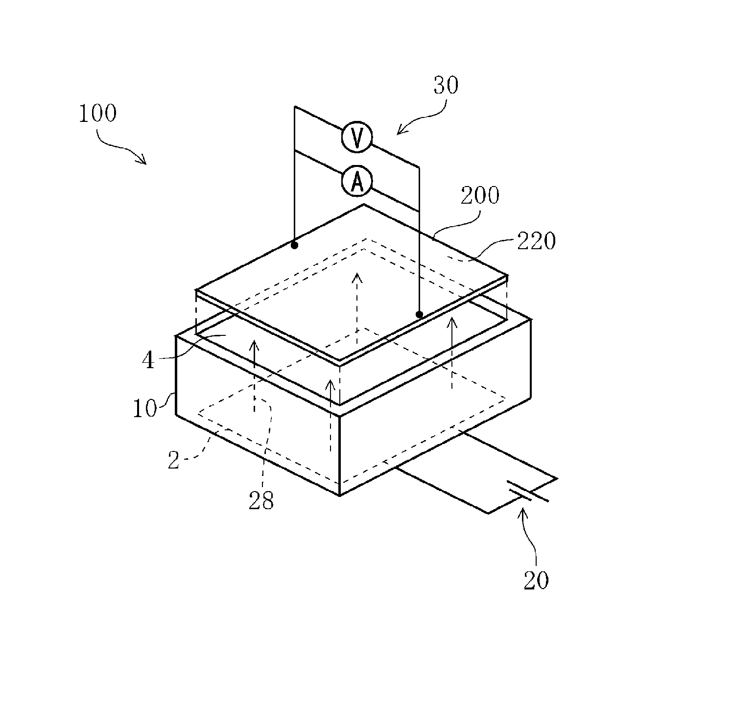
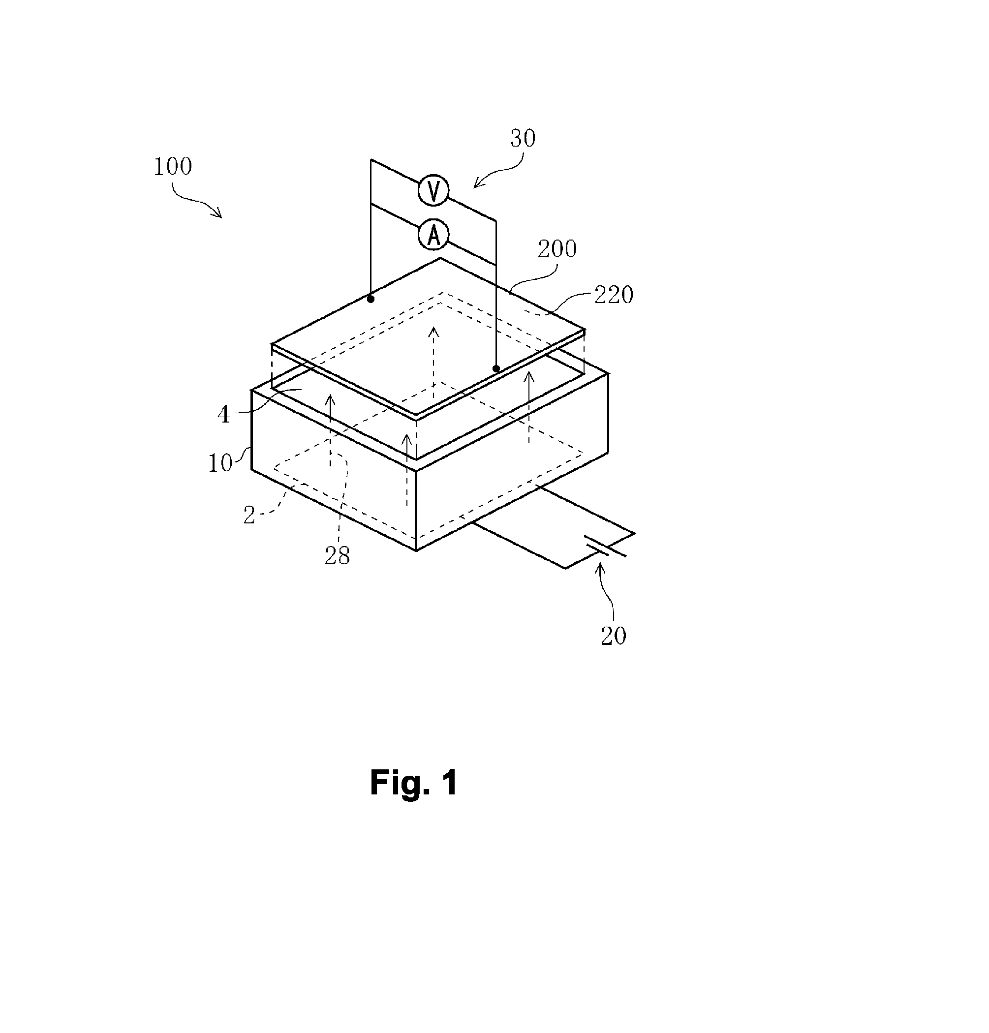
[0028]FIG. 1 is a perspective view showing a schematic configuration of a solar cell inspection device 100 of the present embodiment. The solar cell inspection device 100 of the present embodiment includes a solar simulator 10, a light quantity control section 20, and an electrical measurement section 30. The light quantity control section 20 is connected to the solar simulator 10, and controls the intensity of light 28 emitted by an array of light emitters 2 in the solar simulator 10. In addition, the electrical measurement section 30 is electrically connected to a solar cell to be measured 200 (hereinafter referred to as a “solar cell 200”), and measures current / voltage characteristics (I-V characteristics) while applying an electric load to the solar cell 200. The solar cell inspection device 100 emits the light 28 having a predetermined irradiance set by the solar simulator 10 to a light-receiving surface 220 of the solar cell 200 positioned on an effective irradiated region 4. ...


PUM


Abstract

A solar simulator having improved measurement precision, including an array of light emitters having point light emitters planarly arranged in a given range, an effective irradiated region spaced apart from a surface having the array thereon, and a portion which absorbs at least a part of light from a direction which passes through a gap between the individual point light emitters. In a preferred aspect, the light absorption portion includes an absorption surface disposed in at least a part of the gaps between the light emitters. In another preferred aspect, a translucent board holds the light emitters and has a translucent portion corresponding to at least a part of the gaps between the light emitters, and an absorption layer at a position for absorbing light from the direction which passes through the translucent portion.

Description

CROSS-REFERENCE TO RELATED APPLICATIONS[0001]The present application is the national phase of PCT patent application PCT / JP2011 / 052990, filed on Feb. 14, 2011, which claims priority from Japanese patent application 2010-129209, filed on Jun. 4, 2010.FIELD OF THE INVENTION[0002]The present invention relates to a solar simulator and a solar cell inspection device each for inspecting a solar cell. More specifically, the present invention relates to a solar simulator using an array of light emitters including point light emitters, and a solar cell inspection device using the solar simulator.BACKGROUND ART[0003]Conventionally, in order to inspect photoelectric conversion characteristics of a produced solar cell, electrical output characteristics of the solar cell are measured while the solar cell is irradiated with predetermined light. In the measurement, there is used a light emitter device for irradiating the solar cell with light satisfying predetermined conditions, i.e., a solar simu...

Claims


Application Information

Patent Timeline
Patent Type & Authority Applications(United States)
IPC IPC(8): G01R31/26F21V9/02
CPCF21S8/006F21Y2101/02H02S50/10F21V9/02G01R31/26F21Y2105/001H01L2224/48091H01L2224/48137F21Y2105/10F21Y2115/10Y02E10/50H01L2924/00014G01R31/40F21Y2105/16
Inventor OOTO, MASANORIHIGASHI, RYOUICHISAITO, TETSUYA
Owner FUJI ELECTRIC CO LTD
Why Eureka
Try Eureka