Method and system for decreasing noise from wireless repeaters

a wireless repeater and noise reduction technology, applied in the field of wireless communication, can solve the problems of attenuating or otherwise degrading the signal passing over the air interface, cellular wireless communications can suffer from varying levels of signal degradation, and the problem can be even more acute, so as to improve the quality of wireless signal in buildings and elsewher

Inactive Publication Date: 2006-04-25
SPRINT SPECTRUM LLC
View PDF12 Cites 111 Cited by
  • Summary
  • Abstract
  • Description
  • Claims
  • Application Information

AI Technical Summary

Benefits of technology

[0015]As presently contemplated, wireless signal quality in buildings and elsewhere can be improved by employing a portable wireless signal repeater to receive, boost and re-transmit communication signals that are being sent between a base station and a mobile station (or, for that matter, between any sort of wireless access point and a mobile station). In this regard, the wireless signal repeater can operate simultaneously to boost signals on both the forward link (from base station to mobile station) and the reverse link (from mobile station to base station).
[0016]In accordance with an exemplary embodiment of the present invention, the wireless repeater will advantageously include a mechanism to help a user easily determine if the repeater is well positioned, or more particularly to help a user determine how well the repeater is functioning. In particular, the repeater will preferably include an integrated display screen that presents the user with various combinations of (i) a receive signal level, (ii) a transmit signal level, and (iii) a textual indication of signal quality, reflecting in text (e.g., one or more words) how well the repeater is functioning to repeat wireless signals.
[0017]By simply referring to the display screen, a user can thus readily determine whether the repeater is functioning adequately to boost wireless signal strength. And if the repeater is not functioning as desired, the user can then simply move the repeater around until the display screen reflects acceptable or normal performance. In this manner, the user can easily optimize the performance of the repeater so as to improve the quality of wireless communications.
[0020]As yet another example, when the repeater is receiving a signal that is weak but sufficient to be amplified and output, the receive level may indicate low or weak input signal strength, the transmit level may indicate a respective output signal strength, and the textual indication of signal quality may read “WEAK SIGNAL” or the like. Advantageously, this could indicate to the user that the repeater is functioning alright but not as well as it could. In response, the user can then conveniently move the repeater around until the display screen reflects better RF operation.
[0021]And as still another example, when the repeater is receiving a signal that exceeds a defined threshold of signal strength (such as a maximum level for safe operation of the repeater) or that the repeater cannot amplify and transmit without encountering feedback oscillation, the receive level may indicate full input signal strength, the transmit level may indicate unacceptable / no transmit signal, and the textual indication of signal quality may read “SIGNAL TOO STRONG” or the like. Advantageously, this could then indicate to the user that the repeater is not functioning properly in its currently location. And in response, the user can then conveniently move the repeater around until the display screen reflects adequate RF operation.

Problems solved by technology

Unfortunately, however, cellular wireless communications can suffer from varying levels of signal degradation as signals are carried over the air interface between the mobile station and the base station.
Further, obstructions such as buildings and foliage can attenuate or otherwise degrade signals passing over the air interface.
When a mobile station operates within a building, the problem can be even more acute, as the structure of the building can further diminish the signal.
In a worst case scenario, forward link signals that ultimately arrive at a mobile station within a building may be too weak to be detected and / or used by the mobile station.
As a result, service could be unavailable and wireless communications could be blocked or dropped.
This is clearly a problem for cellular wireless carriers who are seeking to promote in-building use of their service.
A disadvantage with this approach, however, is that the increased power can lead to increased interference in adjacent cells.
This, in turn, can decrease the capacity of the wireless network.
The power increase can also interfere with other wireless devices in use around the base station.
The magnitude of the power increase proportionally affects the amount of interference produced by the base station, with a greater power increase causing a greater interference.
Also, this approach would only solve half of the problem.
It would not aid the base station in receiving a signal from a mobile station.
A disadvantage with this latter approach, however, is that cabling is often difficult and expensive to install.
This is especially true in buildings where cabling may have to be installed inside walls or in other difficult to access areas.
Further, another disadvantage with this approach is its inflexibility resulting from the use of dedicated wired connections.
In particular, a wired network is not easy to reconfigure, as additional cabling must be installed.

Method used


Image

  • Method and system for decreasing noise from wireless repeaters
  • Method and system for decreasing noise from wireless repeaters
  • Method and system for decreasing noise from wireless repeaters

Examples


Embodiment Construction

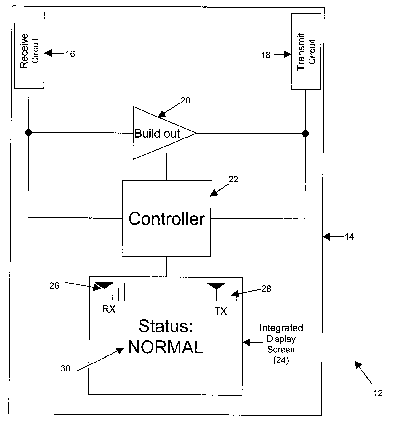
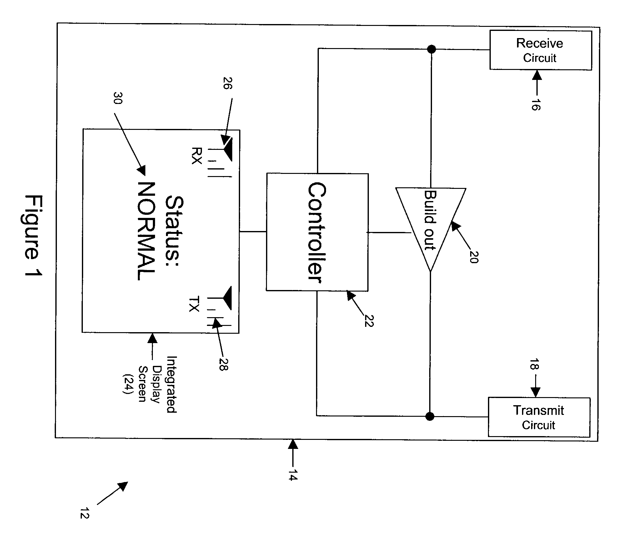
[0036]Referring to the drawings, FIG. 1 is a simplified block diagram illustrating components of a wireless signal repeater 12 made in accordance with an exemplary embodiment of the invention. As shown in FIG. 1, repeater 12 preferably has an outer housing or case 14 in or on which various components are located. Illustrated within housing 14 are a receive circuit 16, a transmit circuit 18, a build-out circuit 20, a controller 22, and a display screen 24. In the arrangement shown, receive circuit 16 is coupled with an input of build-out circuit 20 and with controller 22, and transmit circuit 18 is coupled with an output of build-out circuit 20 and with controller 22. In addition, controller 22 is coupled with display screen 24.

[0037]Each of these components can take various forms. Therefore, particular descriptions of these components in this specification should be viewed as examples only. Further, the arrangement and functions of these components can vary, additional components co...


PUM


Abstract

A wireless signal repeater that cuts off output transmission when the repeater is receiving less than a threshold level of input signal strength (e.g., too low or nonexistent). When operated in the reverse link of a cellular wireless system, the repeater advantageously reduces transmission of noise toward a cellular base station when the repeater is receiving no (or insufficient) signal from the a mobile station. Similarly, when operated in the forward link direction of a cellular wireless system, the repeater advantageously reduces transmission of noise toward a mobile station when the repeater is receiving no (or insufficient) signal from a base station.

Description

REFERENCE TO RELATED APPLICATION[0001]This is a continuation of U.S. patent application Ser. No. 10 / 097,415, filed on Mar. 14, 2002.BACKGROUND[0002]1. Field of the Invention[0003]The present invention relates to wireless communications and, more particularly, to wireless signal repeaters. Such repeaters can be usefully employed to enhance wireless communications of various types. For purposes of example, this description will focus mainly on cellular wireless communications, such as CDMA communications for instance.[0004]2. Description of Related Art[0005]Cellular wireless is an increasingly popular means of personal communication in the modern world. People are using cellular wireless networks for the exchange of voice and data over cellular telephones, personal digital assistants (PDAs), cellular telephone modems, and other devices. In principle, a user can seek information over the Internet or call anyone over a public switched telephone network (PSTN) from any place inside the c...

Claims


Application Information

Patent Timeline
Patent Type & Authority Patents(United States)
IPC IPC(8): H04B7/185
CPCH04B17/23H04B7/15535
Inventor YARKOSKY, MARK L.
Owner SPRINT SPECTRUM LLC
Why Eureka
Try Eureka