Downlight apparatus

a technology of led downlight and downlighting, which is applied in the direction of fixed installation, lighting and heating apparatus, lighting support devices, etc., can solve problems such as heat dissipation

Active Publication Date: 2021-01-19
XIAMEN ECO LIGHTING CO LTD
View PDF11 Cites 0 Cited by
  • Summary
  • Abstract
  • Description
  • Claims
  • Application Information

AI Technical Summary

Benefits of technology

[0009]In addition, the driver plate may also have wireless communication circuit. An antenna of the wireless communication circuit is disposed at the side of the light source plate, instead of being disposed on the driver plate so as to improve wireless signal quality.
[0016]By using such design, it would be easier for users to replace a desired reflective cup. Additional fixing structure may also be used to enhance stability of the downlight apparatus.
[0020]In some embodiment, the terminal portion of the tube body is attached with a heat sink. A cover may be used for covering and protecting the driver plate.
[0030]In some embodiments, the reflective cups have different colors. Users may install reflective cups with different colors for changing the overall luminous effect.
[0032]In some embodiments, the reflective cup may include a light guide for guiding a light forming a light guide visual effect. For example, the reflective cup is made of PMMA material for guiding light into the light guide and escaping the light at desired positions, e.g. forming a ring visual effect.

Problems solved by technology

With LED technology, there are several new technology issues like heat dissipation not seen in traditional light devices.

Method used


Image

  • Downlight apparatus
  • Downlight apparatus
  • Downlight apparatus

Examples


Embodiment Construction

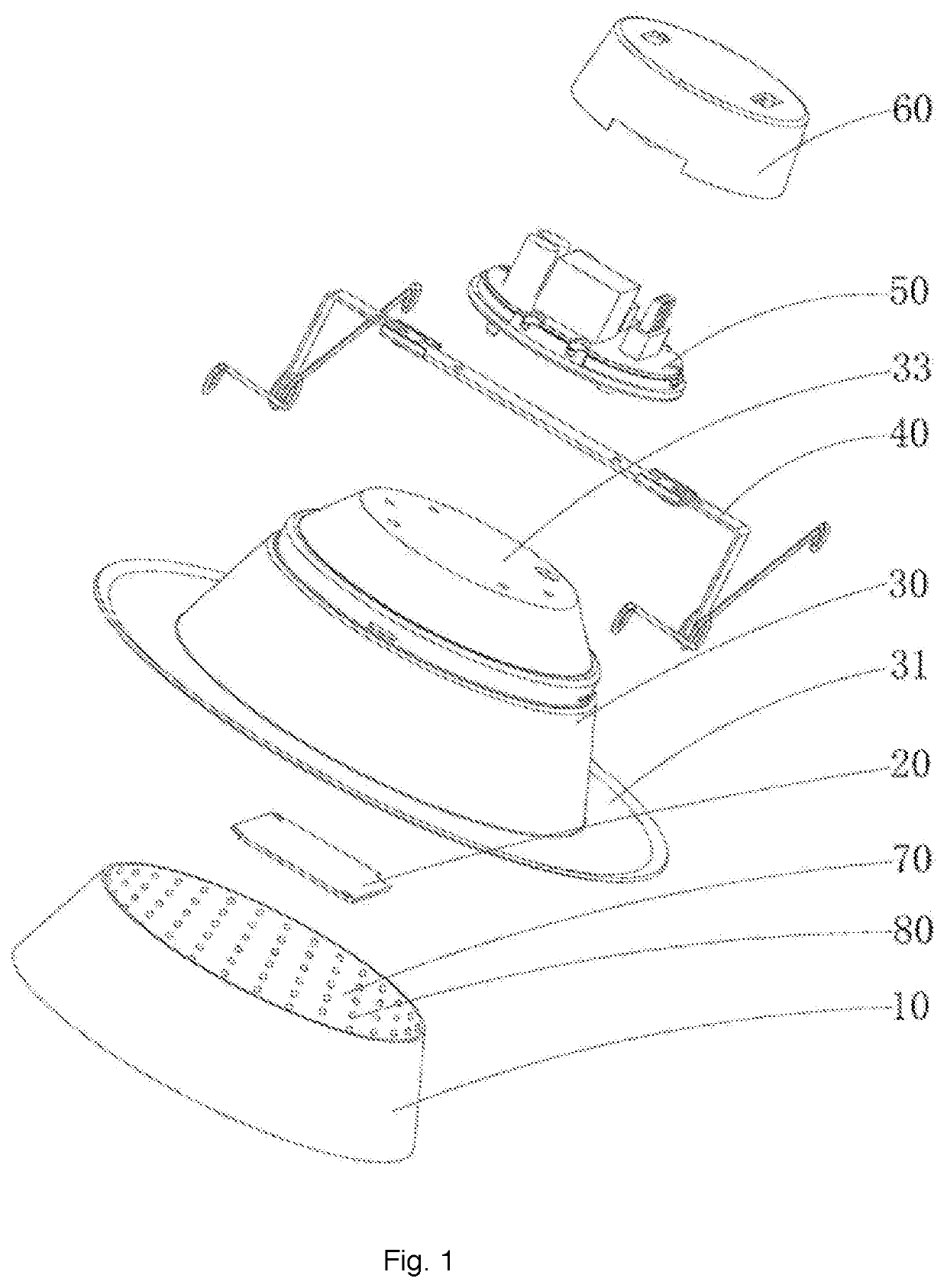
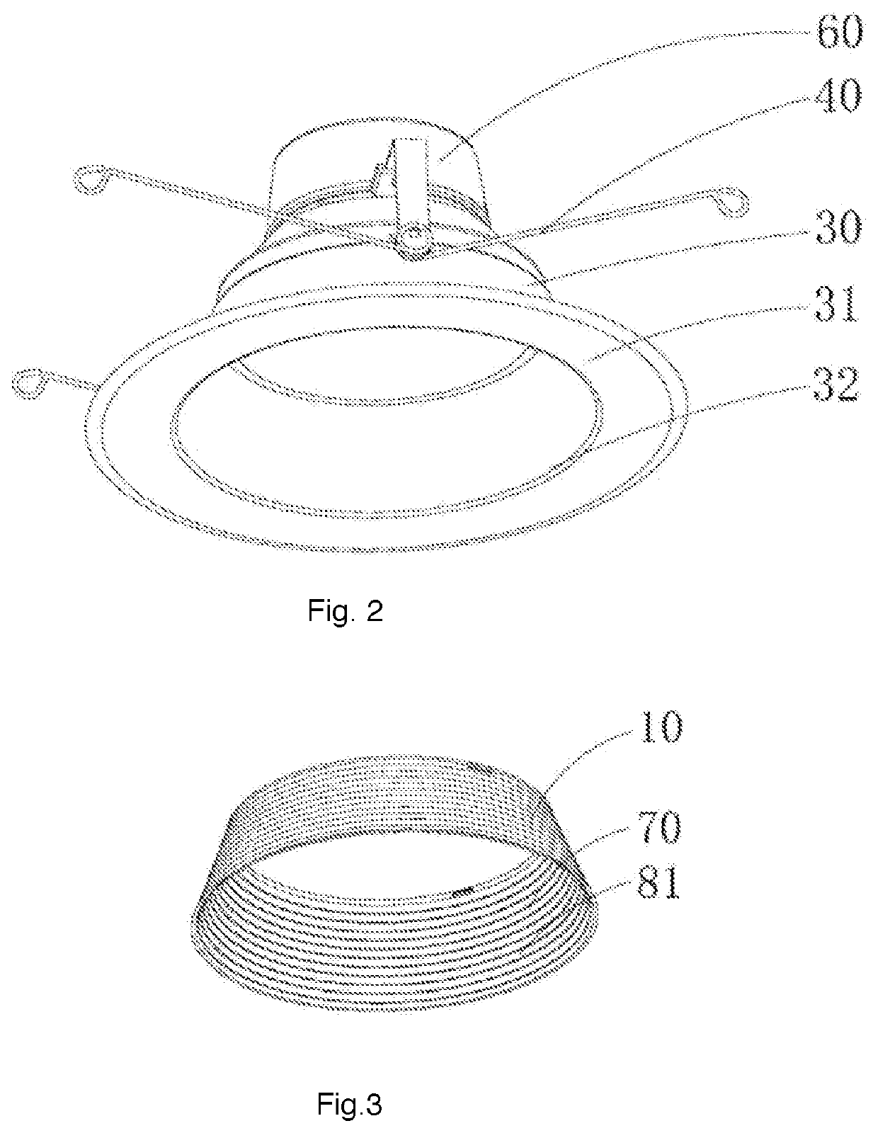
[0044]Please refer to FIG. 1 to FIG. 4, which illustrate a downlight apparatus. The downlight apparatus includes a driver plate 50, a tube body 30 and light source plate 20.

[0045]The tube body 30 has an opening 32 and a terminal portion 33. The terminal portion 33 and the opening 32 are two opposite ends of the tube body 30.

[0046]The driver plate 20 is disposed on an exterior surface of the terminal portion 33 and the light source plate 20 is disposed on an interior surface of the terminal portion 33.

[0047]The light source plate 20 and the driver plate 50 are electrically connected so that the driver plate 20 supplies a driving current to the light source plate 20 to emit light escape from the opening 32.

[0048]The tube body 30 may be made of one heat conductive material as an unibody component or multiple components assembled together. For example, metal fins may be attached to a plastic housing to form the tube body 30.

[0049]By placing the driver plate 50 outside the tube body 30 a...


PUM


Abstract

A downlight apparatus has a tube body, a driver plate, a light source plate, a detachable attaching structure and a set of replaceable reflective cups. The tube body has an opening and a terminal portion opposite to the opening. The driver plate is disposed on an exterior surface of the terminal portion of the tube body. The light source plate is disposed on an interior surface of the terminal portion of the tube body. The detachable attaching structure is disposed in the opening of the tube body. One of the replaceable reflective cups is selectively detachably attached to the detachable attaching structure.

Description

FIELD OF INVENTION[0001]The present invention is related to a LED light apparatus and more particularly related to a LED downlight apparatus.BACKGROUND[0002]Different downlight apparatuses are widely used in various working and living environments. Usually, a cavity or an installation box is disposed on a ceiling. A back portion of the downlight is placed in the cavity or the installation box.[0003]When LED (Light Emitted Diode) technologies keep developing, more and more downlight apparatuses use LED light sources. With LED technology, there are several new technology issues like heat dissipation not seen in traditional light devices. On the other hand, LED technologies also have certain benefit not available in traditional light devices.[0004]It is therefore helpful to find out a better solution to decrease the problem of LED technology and use the benefit of LED technology.SUMMARY OF INVENTION[0005]According to an embodiment, a downlight apparatus includes a tube body, a driver p...

Claims


Application Information

Patent Timeline
Patent Type & Authority Patents(United States)
IPC IPC(8): F21S8/00F21S8/02F21V21/04F21V17/00F21V23/00F21V7/00F21V29/70F21Y115/10
CPCF21S8/026F21V7/00F21V17/002F21V21/04F21V23/006F21V29/70F21Y2115/10
Inventor ZENG, MAOJINYU, QIQING
Owner XIAMEN ECO LIGHTING CO LTD
Why Eureka
Try Eureka